Table of Contents
Advertisement
Quick Links
Advertisement
Table of Contents

Related Manuals for IFM Electronic efector 250 O2M20 Series

Summary of Contents for IFM Electronic efector 250 O2M20 Series
- Page 1 Operating instructions Robust camera system with analogue video output O2M20x...
-
Page 2: Table Of Contents
Contents 1 Preliminary note �������������������������������������������������������������������������������������3 1�1 Symbols used ����������������������������������������������������������������������������������3 1�2 Warning signs used �������������������������������������������������������������������������3 2 Safety instructions ���������������������������������������������������������������������������������4 2�1 General ��������������������������������������������������������������������������������������������4 2�2 Target group ������������������������������������������������������������������������������������4 2�3 Electrical connection ������������������������������������������������������������������������4 2�4 Tampering with the device ���������������������������������������������������������������5 3 Functions and features ��������������������������������������������������������������������������6 3�1 Features at a glance ������������������������������������������������������������������������6 4 Installation����������������������������������������������������������������������������������������������8 4�1 Mounting accessory �������������������������������������������������������������������������8... -
Page 3: Preliminary Note
1 Preliminary note 1.1 Symbols used ► Instruction > Reaction, result […] Designation of keys, buttons or indications → Cross-reference Important note Non-compliance can result in malfunction or interference� Information Supplementary note 1.2 Warning signs used WARNING Warning of serious personal injury� Death or serious irreversible injuries may result�... -
Page 4: Safety Instructions
2 Safety instructions 2.1 General These instructions are part of the device� They contain texts and figures concerning the correct handling of the device and must be read before installation or use� Observe the operating instructions� Non-observance of the instructions, operation which is not in accordance with use as prescribed below, wrong installation or incorrect handling can seriously affect the safety of operators and machinery�... -
Page 5: 2�4 Tampering With The Device
The connection terminals may only be supplied with the signals indicated in the technical data and/or on the device label and only the approved accessories of ifm electronic may be connected� 2.4 Tampering with the device In case of malfunctions or uncertainties please contact the manufacturer�... -
Page 6: Functions And Features
3 Functions and features The camera serves for monitoring of areas outside of the field of view in mobile machines and utility vehicles� The connection and the visualisation of the images are made via dialogue modules with graphics capabilities� The camera works with a nested PAL25 fps 720H x 576V (active 720 x 480) video signal and permanently provides images to the connected dialogue module�... - Page 7 • Resistance to materials in use for transport vehicles such as: Medium Concentration Ammonia Isopropanol 5���10 % Soap water min� 50 per cent by volume of soap Alkaline defatting Concentrations as found for use in high-pressure compounds cleaning devices • Protection rating IP68 to IEC 60529 (10 m water depth / 30 min) • Protection rating IP69K to DIN 40050-9 • IEC 60068-2-52 (cyclic salt spray test) • Anodised, weather-proof aluminium housing...
-
Page 8: Installation
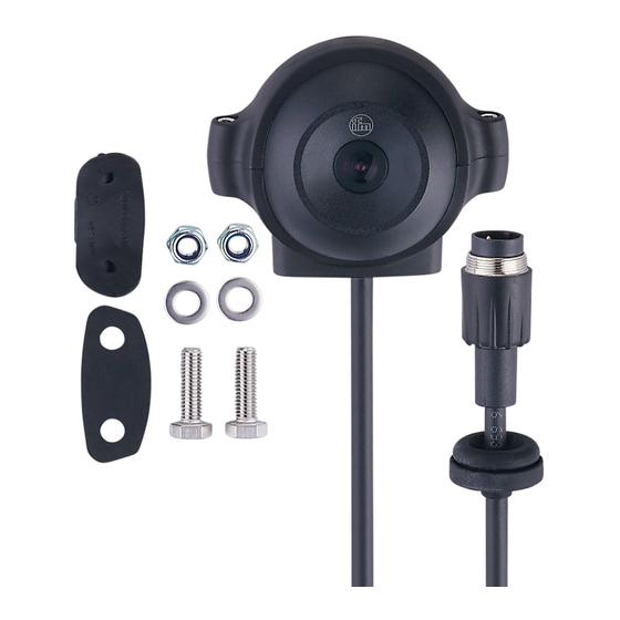
4 Installation 4.1 Mounting accessory ► The unit is supplied with an E2M210 universal mounting clamp� Other mounting accessories are available as alternative� You can find more information about the available accessories at: www.ifm.com → New search → O2M200 → Accessories or directly www.ifm.com → New search → e.g. E2M210 4.2 Mounting dimensions The supplied universal mounting clamp has a borehole spacing of 25 mm�... -
Page 9: 4�3 Installation And Adjustment Of The Camera
4.3 Installation and adjustment of the camera Installation (example) 1� Determine a suitable installati- on location (→ 4.4 Installation location)� 2� Bore the holes for the lower part of the universal mounting clamp� Borehole spacing = 25 cm� 3� Fix the lower part of the mounting clamp with the M6 screws, washers and self-locking nuts supplied with the unit�... -
Page 10: 4�4 Installation Location
4.4 Installation location ► Mount the camera in front of or above the area to be monitored� The size of the area to be monitored depends on the operating distance: Field of view size (2 m operating distance) O2M200 / O2M201 Figure 1: Operating distance and field of view size (78°... - Page 11 Field of view size (2 m operating distance) O2M202 / O2M203 Figure 2: Operating distance and field of view size (115° angle of aperture) 1� Operating distance 2� Width of field of view 3� Height of field of view 2�2 6�0 4�4 The values indicated in figure 2 are theoretical values and can be diffe-...
-
Page 12: Electrical Connection
► Avoid installation in niches, observe the angle of aperture of the lens� ► Avoid back light� ► Do not position lighting elements directly facing the camera lens� ► Mount the device in such a way that the cables / connectors are connected from below�... -
Page 13: 5�2 Voltage Supply And Operational Availability
5.2 Voltage supply and operational availability Power Video signal Lens heating supply < 6 V DC > 6 V DC > 7 V DC 20 % heating power > 8 V DC 40 % heating power 12���33 V DC 100 % heating power The overvoltage protection switches the camera and the heating element off�... -
Page 14: 5�3�1 Connection To The Dialogue Module
5.3.1 Connection to the dialogue module ► Use adapter cables and, if necessary, connection cables� Connection principle: O2M20x camera at the dialogue module, e�g� CR1083 Display Camera Display 1� M16 connection cable 2� M12 ↔ M16 adapter cable 3� 8���32 V * 4� 0 V * 5�... - Page 15 Connection principle: Two O2M20x cameras at the dialogue module, e�g� CR1083 Display Cameras Display 1� M16 connection cable 2� M12 ↔ 2 x M16 Y adapter cable 3� 8���32 V * 4� 0 V * 5� GND (screen) * Core colours of ifm adapter cables: 3 = RD (red); 4 = BK (black); GND = GY (grey) You find more information about adapter or connection cables at: www.ifm.com→ New search → e.g. O2M200 → Accessories...
-
Page 16: 5�4 Interference Due To External Influences
5.4 Interference due to external influences Faulty or insufficient radio interference suppressors in electrical equipment, such as inverters or generators, as well as voltage fluctuations when switching on/off electric loads may lead to problems with the image transmission�... -
Page 17: Maintenance, Repair And Disposal
6 Maintenance, repair and disposal Keep the lens window of the camera free from soiling� Soiling may considerably affect the image quality! ► To clean the lens window, do not use any detergents or solvents which might damage the front glass� ►... - Page 18 ifm weltweit • ifm worldwide • ifm à l’échelle internationale http://www.ifm.com e-mail: info@ifm.com Service hotline: 0800 16 16 16 4 (only Germany, Mon-Fri from 7�00-18�00 h)
Need help?
Do you have a question about the efector 250 O2M20 Series and is the answer not in the manual?
Questions and answers