
Summary of Contents for Veeder-Root 847490-104
- Page 1 (217) 352-9330 | Click HERE Find the Veeder-Root 330749-001 at our website:...
- Page 2 Manual No: 576013-632 Revision: C ● Probe/Thermistor Interface Module Installation Guide...
- Page 3 Notice Veeder-Root makes no warranty of any kind with regard to this publication, including, but not limited to, the implied warranties of merchantability and fitness for a particular purpose. Veeder-Root shall not be liable for errors contained herein or for incidental or consequential damages in connection with the furnishing, performance, or use of this publication.
-
Page 4: Table Of Contents
Table of Contents Introduction .......................1 Related Manuals ....................1 Contractor Certification Requirements ............1 Safety Precautions ...................1 Module Positions and Labeling ...............2 Figure 1 - Console Interface Module Bays ..............2 Circuit Directory ....................3 Figure 2 - Modular Console System Circuit Directory ..........3 Installing Probe/Thermistor Interface Module - I.S. - Page 5 Table of Contents...
-
Page 6: Introduction
576013-623 TLS-3XX Series Consoles System Setup Manual Contractor Certification Requirements Veeder-Root requires the following minimum training certifications for contractors who will install and setup the equipment discussed in this manual: Level 1 Contractors holding valid Level 1 Certification are approved to perform wiring and conduit routing, equipment mounting, probe and sensor installation, tank and line preparation, and line leak detector installation. -
Page 7: Module Positions And Labeling
Probe/Thermistor Interface Module Installation Guide Module Positions and Labeling WARNING The equipment is used in location where lethal voltages and explosive vapors or flammable fuels may be present. Care must be taken when installing, servicing or replacing parts in the system or serious injury or death from explosion, fire or shock may occur. -
Page 8: Circuit Directory
Probe/Thermistor Interface Module Installation Guide Module Positions and Labeling 3. Once a device has been wired to certain terminals on a connector and the system has been programmed, the wires from that device may not be relocated to other terminals without reprogramming the system. Grounding Probe and Sensor Shields Probe and sensor cable shields are grounded at the console only. -
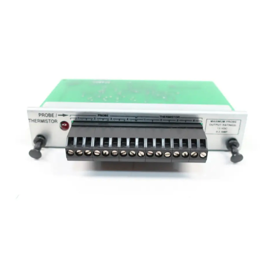
Page 9: Installing Probe/Thermistor Interface Module - I.s. Bay
Probe/Thermistor Interface Module Installation Guide Installing Probe/Thermistor Interface Module - I.S. Bay Installing Probe/Thermistor Interface Module - I.S. Bay PROBE THERMISTOR PROBE / MAXIMUM PROBE THERMISTOR OUTPUT RATINGS: 13 VDC 0.2 AMP PROBE / THERMISTOR INTERFACE MODULE Not Used Attach Cable Shields to Ground Lug Closest to Conduit Entry Console Rigid Conduit... - Page 11 Veeder-Root has sales offices around the world to serve you. Headquarters England Hydrex House, Garden Road 125 Powder Forest Drive Simsbury, CT 06070-7684 Richmond, Surrey TW9 4NR Tel: (860) 651-2700 Tel: +44 (0) 20 8392 1355 Fax: +44 (0) 20 8878 6642 Fax: (860) 651-2719 Email: marketing@veeder.com...
Need help?
Do you have a question about the 847490-104 and is the answer not in the manual?
Questions and answers