
Related Manuals for Agromehanika AGP 1000 EN


Summary of Contents for Agromehanika AGP 1000 EN
- Page 1 Rev.03/2017 The company AGROMEHANIKA reserves the rights to change the design or change the product without any obligation on informing the client before or after the changes have been made.
-
Page 3: Table Of Contents
USER MANUAL TABLE OF CONTENTS: ES STATEMENT OF CONFORMITY ....................4 ES STATEMENT OF CONFORMITY ....................5 1 IN GENERAL ............................. 6 2 GENERAL SAFETY GUIDELINES AND WARNINGS ............. 7 3 INSTRUCTIONS FOR SAFE OPERATION AND SAFETY WARNINGS ........ 8 SAFETY LABELS ............................... - Page 4 9.12 NOZZLE BRACKETS .............................. 28 10 VALVE ADJUSTMENTS ......................29 10.1 MIST BLOWER AGP 1000 PE..........................29 10.2 MIST BLOWER AGP 1000 EN, AGP 1500 EN, AGP 2000 EN ................30 11 OPTIONAL EQUIPMENT ......................31 11.1 SURFACE CLEANING SET ............................ 31 11.2 STRAINER FLUSHER ..............................
- Page 5 USER MANUAL 15.2 COLOUR ..................................46 15.3 TANK ................................... 46 15.4 PRESSURE REGULATOR ............................46 15.5 TUBE JOINTS ................................46 15.6 SCREWS ..................................47 15.7 OTHER PARTS ................................47 15.8 PROTECTION AGAINST FREEZING ........................47 15.9 PUMP ..................................47 15.10 DRIVE/TRANSMISSION SHAFT ........................... 47 16 POSSIBLE ERRORS ........................
-
Page 6: Statement Of Conformity
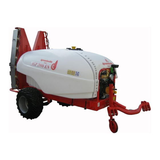
USER MANUAL ES STATEMENT OF CONFORMITY Manufacturer: AGROMEHANIKA, proizvodnja in trgovina Kranj d.d. Hrastje 52 a, KRANJ, SLOVENIJA declares that the products: SPRAYER AGP 1000 EN (ENU) SPRAYER AGP 1500 EN (ENU) SPRAYER AGP 2000 EN (ENU) is manufactured in accordance with: 1. -
Page 7: Statement Of Conformity
USER MANUAL ES STATEMENT OF CONFORMITY Manufacturer: AGROMEHANIKA, proizvodnja in trgovina Kranj d.d. Hrastje 52 a, KRANJ, SLOVENIJA declares that the products: SPRAYER AGP 1000 PE is manufactured in accordance with: 1. Directive on Machinery 2006/42/EC; 2. Directive 2009/127/EC amending Directive 2006/42/EC with regard to machinery for pesticide application;... -
Page 8: In General
We would like to thank you for your trust, which you have shown by buying the sprayers appliance for chemical plant protection of the company AGROMEHANIKA. The reliability and efficiency of the appliance depends on how you will take care of the appliance. We advise you to read and consider this instruction manual carefully before connecting the appliance to the tractor. -
Page 9: General Safety Guidelines And Warnings
USER MANUAL water which temperature is higher than 40 °C or lower than 5 °C; all kinds of lacquer or varnish; fast dissolving diluents; oil or grease; liquids that contain granulates or hard swimming parts. 2 GENERAL SAFETY GUIDELINES AND WARNINGS This sign indicates a warning or important instruction. -
Page 10: Instructions For Safe Operation And Safety Warnings
USER MANUAL 3 INSTRUCTIONS FOR SAFE OPERATION AND SAFETY WARNINGS 3.1 SAFETY LABELS The sign on the left is a safety-alert symbol and is normally placed on the machine together with other labels. Comply with the instructions for safety, also in responding to emergency cases. 3.2 CONSIDERING THE SAFETY RULES Read the instructions considering the safety rules in the operation manual of your machine very carefully. -
Page 11: Safety When Handling Chemical Agents
USER MANUAL 3.5 SAFETY WHEN HANDLING CHEMICAL AGENTS Be very careful when handling chemical agents and in this way avoid possible injuries or damages done as to you as well as to the environment: Be very careful when handling chemical agents. Make sure that you do not come in direct contact with the chemical agents. -
Page 12: Evaluation Of Danger Signs According To Danger
USER MANUAL In case you have a certain medical problem in the time while using the chemical agents, consult your personal physician and try to contact the selling agent who is responsible for your chemical agents. If you have an accident which involves a chemical agent, we advise you to do the following: o eyes and skin: wash with plenty of fresh water;... -
Page 13: Danger Caused By Liquids Under High Pressure
USER MANUAL 3.8 DANGER CAUSED BY LIQUIDS UNDER HIGH PRESSURE The liquid which leaks from the pipes can be under high pressure and can cause injuries to your skin, even more; it can cause dangerous injuries if the liquid spreads under your skin. -
Page 14: Breathing Protection
USER MANUAL 3.11 BREATHING PROTECTION There are many different types of filters available that can protect you against inhaling chemicals. It is recommended to use masks that protect the whole face and are fitted with combinations of different filters (filter for gas-smoke). An even more efficient protection can be achieved by means of a protection helmet in which overpressure can be created. -
Page 15: Maintenance Of The Protection Equipment
USER MANUAL 3.13 MAINTENANCE OF THE PROTECTION EQUIPMENT After every single use thoroughly clean your protection equipment. Wash the mask, boots, gloves and working overall with mild soap water and let them dry. Store your protection equipment in a dry, cold and clean room. Never store your protection equipment in the same room as the chemicals. -
Page 16: Driving Along Roads And Streets
USER MANUAL Do not enter the reservoir to repair or clean it. Support and safely mount all parts that need to be lifted during maintenance. Keep all of the sprayer’s parts in good condition. Repair eventual damages immediately. Replace worn and damaged parts. Remove excess oil, grease or any other debris. Disconnect the battery before you start to adjust the electrical system or perform welding on the machine. -
Page 17: Safety Warning Labels On The Machine And In The Manual
USER MANUAL 4 SAFETY WARNING LABELS ON THE MACHINE AND IN THE MANUAL You can find certain safety and warning signs in this instruction manual that are also attached to the machine. Take a closer look at them in order to work safely. Follow the instructions and advice concerning precautions listed below. -
Page 18: Description
USER MANUAL 5 DESCRIPTION Sprayers, to which this manual applies, are of modern concept, with polyethylene tanks, rounded edges, smooth interior walls and inclined bottoms. The sprayer construction ensures a short barycentre distance between the tractor and machine, a well-stirred spray agent mixture, a complete emptying of the tank, and a simple cleaning process. -
Page 19: Transportation Of The Machine
USER MANUAL 5.2 TRANSPORTATION OF THE MACHINE During transport and if the sprayer is loaded or unloaded from the lorry, make use of the fastening points of the standard three-point system on the sprayer or, if you are using a forklift, the lower part of the supporting framework. -
Page 20: Function Scheme
USER MANUAL 6 FUNCTION SCHEME 1. Outlet valve 2. Three-way selector valve 3. Selector valve 4. Pump 5. Suction filter with valve 6. Main tank 7. Flushing tank 8. Clean water tank for washing hands 9. Valve for opening of separate spraying sections 10. -
Page 21: Connecting The Sprayer To The Tractor
USER MANUAL 7 CONNECTING THE SPRAYER TO THE TRACTOR All pull-type sprayers are designed for connecting to the tractor three-point system of I. or II. categories (diameter of clamp bolts 22 or 28 mm). 7.1 WITH THE HELP OF ADJUSTABLE JACK Shape and position of connector on the sprayer enable hitching of the machine to the tractor in more ways –... -
Page 22: On Tractor Connection (Traction) Hook
USER MANUAL 7.2 ON TRACTOR CONNECTION (TRACTION) HOOK If the sprayer traction jack must be pulled out fully, never hitch the sprayer on the tractor bottom lift arms, but use the connection (traction) hook on the rear part of the tractor instead. After installing the sprayer, raise the two lift arms to the operating height or until the sprayer’s chassis is positioned more or less horizontally (the front and rear of the sprayer are equally distanced from the ground) and fasten them with side tension devices to prevent sideward oscillation of the sprayer. -
Page 23: Mounting Of The Drive Shaft (Cardan Shaft)
USER MANUAL 8 MOUNTING OF THE DRIVE SHAFT (CARDAN SHAFT) 8.1 OPERATOR’S SAFETY To avoid possible accidents and personal injuries please follow the instructions and recommendations written below! Before mounting (connecting of the cardan shaft to the tractor and the sprayer) the drive shaft – cardan shaft, always turn off the engine and remove the start key from its lock. -
Page 24: Detailed Description With Instructions For Use
USER MANUAL 7. Mount the cardan shaft to the tractor and the sprayer. WARNING: Always mount the female end of the cardan shaft to the tractor! Connect the chains in order to avoid rotating of the safety covers! 8. To assure a long reliability of the cardan shaft avoid angles bigger than 15°. -
Page 25: Tank Cover
USER MANUAL 9.2 TANK COVER MAIN TANK LID The tank lid is made of two parts. The smaller part in the centre is designed for more convenient filling of the tank with water. The recommended method is filling with clean water (without any polluting agents). To open the lid, unscrew it to the left;... -
Page 26: Mixing Nozzle
USER MANUAL 9.5 MIXING NOZZLE The sprayer is equipped with one or two mixing nozzles for better mixing of the mixture. The nozzles are mounted in the lower part of the reservoir. The mixing nozzle is controlled by means of the valve which is mounted on the pressure regulator. -
Page 27: Suction Filter
USER MANUAL 9.7 SUCTION FILTER The suction filter is mounted between the reservoir and the pump. Its function is to filtrate the insecticide before it reaches the regulator. The size of the filter is 50 MASH. FILTER INSERT CLEANING (SUCTION FILTER) First, unscrew the yellow plug (3) on the filter lid (2) in counterclockwise direction and pull it out. -
Page 28: Adjustable Axle
USER MANUAL 9.9. ADJUSTABLE AXLE By all sprayers with wheels, the wheel axle is clamped in the chassis in a way that enables continuously variable adjusting of track width. Each axle is sideward fastened with four screws that must be slightly unscrewed for changing the width (the chassis must be lifted from the ground) and pulled out or pushed into the supporting tube of wheel axle for a chosen track width. -
Page 29: Fan With Adjustable Vanes
1940 of the fan. SETTING THE FAN All Agromehanika pull-type sprayers are equipped with a fan rotating in the left, seen from the front side of the fan, or in the driving direction of the tractor. SETTING PROCEDURE: 1. -
Page 30: Nozzle Brackets
USER MANUAL MULTIPLIER The multiplier deals with the momentum transfer from the pump via transmission shaft (PTO) to the fan. Transfer is single-stage with a possibility of rotation shutdown (turning off the fan). FAN SHUTDOWN: The multiplier, with the fan rotating on its shaft, is on its side equipped with a shutdown handle that enables the fan switch-off. -
Page 31: Valve Adjustments
USER MANUAL 10 VALVE ADJUSTMENTS 10.1 MIST BLOWER AGP 1000 PE SPRAYING By way of a three-way valve (5) the liquid flows from the main tank and through the suction filter inside the three-way valve and through the pump (4) into the pressure regulator (10). Open the ball valve (9) on the pump for mixing the spraying agent by means of a mixing nozzle (14). -
Page 32: Mist Blower Agp 1000 En, Agp 1500 En, Agp 2000 En
USER MANUAL 10.2 MIST BLOWER AGP 1000 EN, AGP 1500 EN, AGP 2000 EN SPRAYING Spray agent is released from the main tank via three-way valve (2) through the filter (5) and the pump (4) into the pressure regulator (10). Open the ball valve on the pump (9) for spray agent mixing with the help of the mixing nozzle (14) and the valve for supplying nozzles sections (20). -
Page 33: Optional Equipment
USER MANUAL PARTIAL CLEANING Partial machine cleaning comprises cleaning the filter (5), pump (4), pressure regulator (10) and spraying nozzles (18), without changing spray agent concentration in the main tank. Switch the three-way valve (2) to the flushing tank (7) and with the selection valve (3) redirect the flow directly to the pump (4). -
Page 34: Strainer Flusher
USER MANUAL 11.2 STRAINER FLUSHER This addition enables a more convenient handling of spray agents. A special nozzle is incorporated in the strainer that directs the fluid flow from the nozzle to the bottom of the strainer, thus flushing the spray agent previously poured in the strainer. -
Page 35: Suction Basket With Suction Tube
USER MANUAL 11.4 SUCTION BASKET WITH SUCTION TUBE 7.2. Three-way selection valve 7. 3. Selection valve Pump 7.1. Suction filter Main tank Pressure regulator 20. Suction basket with suction tube The suction basket is meant for sucking of water out of ponds, streams, fountains, etc. through the filter, the pump and the regulator into the main reservoir. -
Page 36: Long Range Spraying Nozzle Bracket
USER MANUAL 11.5 LONG RANGE SPRAYING NOZZLE BRACKET When the spraying height becomes inadequate due to the height of the fruit trees, the sprayer can be fitted with nozzle brackets for long range spraying. Like the standard brackets, these are equipped with two outlets. -
Page 37: Terrace Spraying Kit
USER MANUAL 11.7 TERRACE SPRAYING KIT The kit is designed for protecting orchards and vineyards planted in terraces; it can also be used for standard plantations. Nozzles on air rectifier are divided into 4 sections: -top left -top right -bottom left -bottom right. -
Page 38: Pressure Regulator
USER MANUAL 12 PRESSURE REGULATOR 12.1 PRESSURE REGULATOR M170 Operation with high-pressure regulator M170 is manual. It can be used for remote manual regulation of machine working parameters from the tractor cabin, which is its advantage. It is used for operating pressures of up to 50 bar and for pumps with maximum flow capacity of 150 l/min. -
Page 39: Pr9 Pressure Regulator
USER MANUAL REMOTE CONTROLLED PRESSURE REGULATION (PR8ECF/2EC) A better version of the regulator (EC label) is apart from manual valve equipped also with an electromagnetic regulation valve, which enables the remote control operating pressure setting (from the cabin). 1- Main regulation valve 6- Main switch (ON-OFF) 2- Solenoid regulation valve for remote pressure 7- Pressure adjustment (+ or -) -
Page 40: Regulator Labelling
USER MANUAL 12.4 REGULATOR LABELLING STANDARD MODELS The pressure regulator label includes the regulator type, information on whether the regulator is equipped with a pressure filter, as well as the number and type of diverter valves. Example: The label PR8ECF/2EC identifies the type PR8 pressure regulator with remote controlled pressure regulation, high-pressure filter (F mark) and two solenoid diverter valves (numerical mark + EC). - Page 41 USER MANUAL PR8: IMPORTANT: When reducing the pressure, take care not to loosen the nut too much (when you wish to reduce the pressure to below 1 bar), otherwise the nut may fall off the regulator along with some other essential regulator components. The PR8 regulation valve enables manual adjustment of operating pressure from 0 to 40 bar and its maximum flow capacity is 160 l/min at the operating pressure of 2 bar.
- Page 42 USER MANUAL PRESSURE FILTER PR8, PR9: The PR8 and PR9 pressure regulators are equipped with a robust and compact high-pressure filter. Inside the filter there is a filter insert containing a stainless steel mesh of a M40 density. Because the filter does not come with a self-cleaning feature, it must be occasionally opened with a special wrench, which is provided, and cleaned.
-
Page 43: Regulator Operation Adjustment
USER MANUAL M170: The M170 pressure regulator is equipped with two diverter valves (left/right side) that can be opened/closed with a large lever at the front side, which can be rotated by 360°. The lever enables opening and closing of an individual section or both sections together. -
Page 44: Pressure Regulator Maintenance
USER MANUAL PR9: Due to its volume, the User Manual for PR9 pressure regulator is provided as separate booklet to all mist blowers equipped with this regulator and contains all detailed instructions for correct adjustments and use or the pressure regulator. 12.7 PRESSURE REGULATOR MAINTENANCE After every spraying the pressure regulator must be washed with clean water. -
Page 45: Use
USER MANUAL 13.2 USE Before starting the pump drive, make sure the main pressure regulator valve is in a free-flow position (open tank return line). Never turn on the pump’s drive when the setting on the regulator enables full stressing of the pump. - Page 46 USER MANUAL First oil change is done after the initial 100 pump operating hours, then, after every 500 pump operating hours, or at the end of every working season. When changing the oil, also check the state of pressure membranes and replace them with new ones even if they are undamaged. ...
-
Page 47: Cleaning The Machine
USER MANUAL 14 CLEANING THE MACHINE The sprayer must be thoroughly cleaned after every use. Spray agent residue is most conveniently used if it is diluted with clean water and applied on areas already treated. Its concentration should be at least 10 % (10 units of water per one unit of spray agent), the driving speed a bit higher, whereas the working pressure should be lower (5-7 bar, depending on the sprayer). -
Page 48: Maintenance And Storage After Spraying Season
USER MANUAL 15 MAINTENANCE AND STORAGE AFTER SPRAYING SEASON After the end of spraying season, take some time to prepare the sprayer for storage. Before storing it, thoroughly clean the whole sprayer from the outside and inside (pressure regulator, pump, strainers, selection valves, nozzles…). -
Page 49: Screws
USER MANUAL 15.6 SCREWS IMPORTANT: Check the screws, bolts and especially protective bolts, their state and how firmly they are screwed. If necessary, fasten them or replace them with new. 15.7 OTHER PARTS Also other vital parts, such as filter inserts, pouring strainer, additional equipment … must be cleaned, checked for its state and if necessary replaced with new parts. -
Page 50: Possible Errors
USER MANUAL 16 POSSIBLE ERRORS SIGNS FOR POSSIBLE REASON CHECK / REPAIR ERROR There is no liquid damaged or incorrectly check and if necessary replace coming out from the inserted valves in the valves in the pump; nozzles even though pump;... -
Page 51: Technical Data
USER MANUAL 17 TECHNICAL DATA 17.1 MIST BLOWERS WITH STANDARD FAN HOUSING MACHINE LABEL MACHINE TECHNICAL DATA AGP 1000 EN AGP 1500 EN AGP 2000 EN AGP 1000 PE Tank nominal capacity 1000 1500 2000 1000 1099 1622 2127 1099... -
Page 52: Mist Blowers With Air Deflector
USER MANUAL 17.2 MIST BLOWERS WITH AIR DEFLECTOR MACHINE LABEL AGP 2000 MACHINE TECHNICAL DATA AGP 1000 ENU AGP 1500 ENU AGP 2000 ENU ENU-SA OPRUGAMA Tank nominal capacity 1000 1500 2000 2000 1099 1622 2127 2127 Tank Nominal Capacity Flushing Tank Capacity 15,7 Capacity of Tank for Washing Hands... -
Page 53: Technical Residue
USER MANUAL 17.4 TECHNICAL RESIDUE 1000 1500 2000 TECHNICAL RESIDUE EN/ENU EN/ENU EN/ENU diluted 10,50 37,20 45,00 On even ground undiluted 0,60 0,80 2,00 driving to the left 17,60 20,20 22,00 transversal On a driving to the right 17,60 20,20 22,00 12 % driving upwards... -
Page 54: Combination Matrix
USER MANUAL 18 COMBINATION MATRIX FAN HOUSING MIST BLOWER PRESSURE REGULATOR PUMP ADDITIONAL EQUIPMENT DEFLECTOR 03/2017... -
Page 55: General Instructions For Sprinkling
USER MANUAL 19 GENERAL INSTRUCTIONS FOR SPRINKLING 19.1 PREPARATION BEFORE STARTING OPERATION For a successful sprinkling, the appropriate water quantity, right nozzle selection and a precise consumption calculation are of major importance. It is recommended to stick to the following order when it comes to preparing of the sprinkling mixture and sprinkling: Make sure that the sprinkling appliance is in flawless condition. -
Page 56: Types Of Nozzle Inserts
USER MANUAL 20 TYPES OF NOZZLE INSERTS In accordance with the standards, all sprayers of Agromehanika trademark are equipped with ceramic TR type nozzle inserts, made by a renowned German manufacturer LECHLER. Nozzle inserts are designed for all kinds of detailed treating of habitus with protective agents, among which is also spraying with low water consumption. -
Page 57: Different Calculations
USER MANUAL With the help of charts you can define the consumption per hectare with a view to the size of chosen nozzle inserts, operating pressure, driving speed, and interlinear distance in the plantation, or you can define the size of nozzle inserts according to your requirements. CHART 3: Flows of ceramic nozzle inserts LECHLER-TR (l/min) NOTE: NOZZLE FLOWS ARE ALWAYS EQUAL FOR THE SAME LABEL COLOURS OF DIFFERENT TYPES (ST, LU, AD, ID, TR…), AND DIFFERENT NOZZLE MATERIALS. -
Page 58: Some Recommendations
NAVODILO ZA UPORABO Example No. 1: There are 10 pieces of TR-OCHRE nozzle inserts incorporated in the sprayer, working pressure is set at 11 bar, interlinear distance in an orchard is 3.6 m, driving speed is 4.2 km/h. What is the consumption per hectare? Chart 1 shows that the required time for spraying per hectare is 40 min. -
Page 59: Notes
NOTES...
Need help?
Do you have a question about the AGP 1000 EN and is the answer not in the manual?
Questions and answers