Table of Contents
Advertisement
Quick Links
Advertisement
Table of Contents

Subscribe to Our Youtube Channel
Related Manuals for Auditronics ALM-12d

Summary of Contents for Auditronics ALM-12d
- Page 1 ALM-12d Digital Audio Console TECHNICAL MANUAL October 2001...
- Page 2 ALM-12d Digital Audio Console Technical Manual - 1st Edition ® ©2001 Auditronics AUDITRONICS 600 Industrial Drive New Bern, North Carolina 28562 252-638-7000 *a division of Wheatstone Corporation ALM-12d / Oct 2001 R-16 / Dec 1997...
- Page 3 Any modifications not expressly approved in writing by Any modifications not expressly approved in writing by Auditronics could void the user's authority to operate this equipment. Auditronics could void the user's authority to operate this equipment. Auditronics could void the user's authority to operate this equipment.
-
Page 4: Table Of Contents
Analog Stereo Line Level Inputs ................2-3 Digital Stereo Line Level Inputs ................2-3 Producer Talkback Input ................... 2-3 Sources ..................2-3 Faders ....................2-4 Outputs ..................2-4 Mutes and Tallies ................2-4 Other Features ................2-5 Console Layout Drawing ..............2-6 page Contents – 1 ALM-12d / Oct 2001... - Page 5 Meter Section Overview ........................5-4 Tallys ....................5-5 On-Air Tally Circuit ....................5-6 Hook-Ups ..................5-7 Monitor Outputs ......................5-7 Tallys ......................... 5-7 DB Connector Pinout Drawings Monitor Outputs ......................5-8 Tallys ......................... 5-9 page Contents – 2 ALM-12d / Oct 2001...
- Page 6 ON and OFF Buttons ................. 9-7 Phone Section ................9-7 The Phone Section Is Different Than a Normal Fader ....9-7 Select Button ..................9-8 On Air Caller Feed Selection ................9-8 page Contents – 3 ALM-12d / Oct 2001...
- Page 7 ON Logic Input....................9-17 OFF Logic Input....................9-17 Cough Logic Input ................... 9-18 Talkback to CUE Logic Input................9-18 ON Tally Logic Input ..................9-18 Line Port Function ................9-18 Start Logic Input ....................9-18 page Contents – 4 ALM-12d / Oct 2001...
- Page 8 Monitor Switch Card Schematic (MSW-1214) ............10-20 Monitor Switch Card Load Sheet (MSW-1214) ............10-21 Logic Port Board Schematic (LP-1214) ..............10-22 Logic Port Board Load Sheet (LP-1214) ..............10-24 Appendix Replacement Parts List ............... A-2 page Contents – 5 ALM-12d / Oct 2001...
- Page 9 Failsafe Dual Redundant Supply................ 1-7 Energizing......................1-7 Audio and Control Wiring............1-7 Connection Procedures ..................1-8 Digital Audio Connections .................. 1-8 Unbalanced Connections (analog audio) ............1-8 Hand Crimp Tool Wiring Insrtuctions ........1-9 page 1 – 1 ALM-12d / Oct 2001...
-
Page 10: Unpacking The Console
The console extends approximately 6” above the countertop at the meterbridge. Do not connect the ALM-12d console to its power supply (and do not connect the power supply to the AC power line) until instructed to do so. -
Page 11: System Ground
The first step is to ground the console. Note that as supplied from the factory, console rackmount power supply common, audio ground, and the ALM-12d mainframe are connected together at the console, but are NOT connected to electrical ground and the chassis of the power supply. Safety requirements dictate that a positive connection from the console mainframe to electrical ground be made in the completed installation. -
Page 12: Power Supply
Once the system is properly grounded, proceed with the console power supply installation and connection (next section). Power Supplies The ALM-12d console is powered by a Wheatstone Model PSC-D340 If failsafe redundant sup- rackmount power supply. This heavy duty unit occupies three 19” wide... -
Page 13: The Psc-D340 Power Supply
Note that while the AC color. power cord ground wire terminates at the power supply chassis, it does NOT connect to the ALM-12d console common; the console itself must be grounded separately. (See previous section, "System Ground".) Model PSC - D340 Power Supply PHANT –V... - Page 14 For 220-240 V operatin: Disconnect 1 & 3, 2 & 4; Connect 2 & 3. A.C. 115 OR 230 VAC SUPPLY 50-60Hz INPUT CABLE Power Supply Schematic - Sheet 1 of 1 Page 85 RD-12/Aug 2001...
-
Page 15: Failsafe Dual Redundant Supply
Audio and Control Wiring All audio and control I/O connections to the ALM-12d console are made through multipin DB-25 connectors located on the rear panel of the console. The factory supplied hand crimping tool is used for all I/O wiring connections to and from the console (see instruction on the page 1-9). -
Page 16: Connection Procedures
“consumer” digital audio interface is a two wire unbalanced signal typically on a single RCA style connector. To connect SPDIF devices to the ALM-12d console simply wire the SPDIF center conductor (HOT) to the digital input HI pin and SPDIF shell (ground) to the LO pin. Connect the digital input SH at the console end only. -
Page 17: Hand Crimp Tool Wiring Instructions
Note that metallized plastic hoods for each connector are also supplied with the console. (4) Place extractor tip over pin terminal to be removed. page 1 – 9 ALM-12d / Oct 2001... - Page 18 Digital Stereo Line Level Inputs ................2-3 Producer Talkback Input ..................2-3 Sources ..................2-3 Faders ..................2-4 Outputs ..................2-4 Mutes and Tallies ............... 2-4 Other Features ................2-5 Console Layout Drawing ............2-6 page 2 – 1 ALM-12d / Oct 2001...
-
Page 19: Overview
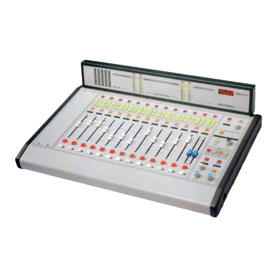
C O N S O L E F E A T U R E S Console Features Overview The ALM-12d console consists of twelve faders with associated switches a dual fader PHONE section, also with associated switches, a MONITOR SEC- TION, a CONTROL SECTION, and a TIMER SECTION. Each section is described below. -
Page 20: Inputs
(-50dBu nominal), stereo line analog (+4dBu balanced), or stereo line digital inputs. The ALM-12d is designed to handle up to eight analog stereo line level inputs. Two other stereo line inputs can be used for stereo signals or can be split to provide four mono mic inputs (two each per stereo line input) instead. -
Page 21: Faders
ON status of one or more inputs. page 2 – 4 ALM-12d / Oct 2001... -
Page 22: Other Features
Check with the person in charge of the technical side of the console to see which of these features apply to your setup, and ignore those that don’t apply. page 2 – 5 ALM-12d / Oct 2001... - Page 23 Logic Port Wiring Considerations ............... 3-7 DB Connector Pinout Drawings Mono Mic Inputs ..................... 3-9 Stereo Line Analog Inputs ..................3-10 Stereo Line Digital Inputs ..................3-11 Logic Control Ports ....................3-12 page 3 – 1 ALM-12d / Oct 2001...
-
Page 24: Overview
All audio and control input and output signals are made via a multi- pin DB-25 connectors mounted on the rear of the console. page 3 – 2 ALM-12d / Oct 2001... -
Page 25: Hook-Ups
+4dBu balanced. A pinout drawing on page 3-10 shows all wiring connec- tions at a glance. DB-25 “LINE IN 1-4” Connector Pin 24 – HI Pin 12 – LO Line 1 Lt In Pin 25 – SH page 3 – 3 ALM-12d / Oct 2001... -
Page 26: Db-25 "Line In 5-8" Connector
Pin 15 – HI Pin 3 – LO Line 8 Lt In Pin 16 – SH Pin 1 – HI Pin 14 – LO Line 8 Rt In Pin 2 – SH page 3 – 4 ALM-12d / Oct 2001... -
Page 27: Db-25 "Line In 9-10, Tb In" Connector
5 – SH Pin 15 – HI Pin 3 – LO AES 7 In Pin 16 – SH Pin 1 – HI Pin 14 – LO AES 8 In Pin 2 – SH page 3 – 5 ALM-12d / Oct 2001... -
Page 28: Logic Control Ports
F A D E R S E C T I O N Logic Control Ports The ALM-12d console has eight LOGIC PORTS located on the rear of the console and can be used to control local machines, such as cart machines, CD players, etc., or with talent panels for mic signals. -
Page 29: Line Port Functions
When wiring a logic input to a machine, the same mechanism, which is the application of 5V in the correct polarity to the inputs plus and minus terminals. The machine will often be the source of the external voltage. Consult the machine’s documentation. page 3 – 7 ALM-12d / Oct 2001... - Page 30 External relays or lower or higher voltage LEDs may also be driven by the outputs. Use current limiting resistors when necessary, do not exceed 24V for the external supply, and always use snubber diodes across con- nected relay coils. page 3 – 8 ALM-12d / Oct 2001...
-
Page 31: Mono Mic Inputs
MIC 2 OUT LO MIC 2 OUT HI MIC 3 OUT SH MIC 3 OUT LO MIC 3 OUT HI MIC 4 OUT SH MIC 4 OUT LO MIC 4 OUT HI page 3 – 9 ALM-12d / Oct 2001... - Page 32 LINE 10 IN LT HI still line level inputs, and they are not LINE 10 IN RT SH internally connected to the four mic LINE 10 IN RT LO preamps. LINE 10 IN RT HI page 3 – 10 ALM-12d / Oct 2001...
- Page 33 AES 5 LO AES 5 HI AES 6 SH AES 6 LO AES 6 HI AES 7 SH AES 7 LO AES 7 HI AES 8 SH AES 8 LO AES 8 HI page 3 – 11 ALM-12d / Oct 2001...
-
Page 34: Logic Control Ports
DIGITAL GROUND DB-25 READY - READY + CONNECTORS DIGITAL GROUND TB - TB + DIGITAL GROUND COUGH - COUGH + DIGITAL GROUND OFF - OFF + DIGITAL GROUND ON - ON + page 3 – 12 ALM-12d / Oct 2001... -
Page 35: Chapter 4 - Phone Section
P H O N E S E C T I O N Phone Section Chapter Contents Overview ..................4-2 Hook-ups ..................4-4 DB Connector Pinout Drawing ..........4-5 page 4 – 1 ALM-12d / Oct 2001... - Page 36 If you don’t want the on air caller feed to be automatically selected in this fashion, press the desired bus assign switch while the phone is still off. This feature may have been disabled by the installer. page 4 – 2 ALM-12d / Oct 2001...
- Page 37 Presence of the signal in the mix-minus buses depends on the phone mix-minus status. All audio input and output signals are made via a multi-pin DB-25 connector mounted on the rear of the console. page 4 – 3 ALM-12d / Oct 2001...
- Page 38 Pin 15 – HI Pin 3 – LO MXM 1 Out Typical DB-25 connector Pin 16 – SH Pin 1 – HI Pin 14 – LO MXM 2 Out Pin 2 – SH page 4 – 4 ALM-12d / Oct 2001...
- Page 39 CALL 2 OUT HI AUDIO GROUND AUDIO GROUND MXM 1 OUT SH MXM 1 OUT LO MXM 1 OUT HI MXM 2 OUT SH MXM 2 OUT LO MXM 2 OUT HI page 4 – 5 ALM-12d / Oct 2001...
- Page 40 Overview ......................... 5-4 Tallys ................... 5-5 On-Air Tally Circuit ....................5-6 Hook-Ups ..................5-7 Monitor Outputs ...................... 5-7 Tallys ........................5-7 DB Connector Pinout Drawings Monitor Outputs ...................... 5-8 Tallys ........................5-9 page 5 – 1 ALM-12d / Oct 2001...
-
Page 41: Control Room Monitor Overview
The source can be any signal appearing at a console input connector, any of the four main buses, either of the caller feed mix-minus buses, or either of the general purpose mix-minus buses. page 5 – 2 ALM-12d / Oct 2001... -
Page 42: Studio Monitor Overview
MUTE the Studio output to prevent the occur- rence of feedback. The installer may have used the Studio pre-fade output to provide a source for studio headphones which will not be affected by the studio mute. page 5 – 3 ALM-12d / Oct 2001... -
Page 43: Meter Section
The level of the signal being metered is indicated by the number of display elements that are lighted. The more elements lighted, the stronger is the signal being displayed. The top three LEDs in each bargraph are red to indicate when page 5 – 4 ALM-12d / Oct 2001... -
Page 44: Tallys
ON status of one or more inputs. Ask the technical person in charge of the console if TALLY 2 is used, and if so, what it is set up to do. page 5 – 5 ALM-12d / Oct 2001... -
Page 45: On-Air Tally Circuit
DB-25 connector mounted on the rear of the console. Connect the on-air light to the external user-provided relay. Do not bring on-air light AC connections to any pin of any connector on the console. page 5 – 6 ALM-12d / Dec 2002 ALM-12d / Oct 2001... -
Page 46: Hook-Ups
Pin 21 - CR Tally N.O. Pin 9 - CR Tally COM. Pin 22 - Analog Ground Pin 7 - Tally 2 N.O. Pin 20 - Tally 2 COM. Pin 8 - Analog Ground page 5 – 7 ALM-12d / Oct 2001... -
Page 47: Monitor Outputs
ST PRE OUT RT LO ST PRE OUT RT HI HDPN OUT LT SH HDPN OUT LT LO HDPN OUT LT HI HDPN OUT RT SH HDPN OUT RT LO HDPN OUT RT HI page 5 – 8 ALM-12d / Oct 2001... -
Page 48: Tallys
LINE 9 IN RT HI LINE 10 IN LT SH LINE 10 IN LT LO LINE 10 IN LT HI LINE 10 IN RT SH LINE 10 IN RT LO LINE 10 IN RT HI page 5 – 9 ALM-12d / Oct 2001... -
Page 49: Chapter 6 - Control Section
C O N T R O L S E C T I O N Control Section Chapter Contents Overview ..................6-2 page 6 – 1 ALM-12d / Oct 2001... -
Page 50: Overview
CHANNEL DISPLAY - shows which fader is being accessed. During a mix-minus status check the display shows “MIXMINUS”. Otherwise the display shows “ALM-12d”. SOURCE DISPLAY - shows the name of the source currently selected for or being selected for the fader. During a mix-minus status check the display shows software revision information. -
Page 51: Chapter 7 - Timer Section
T I M E R S E C T I O N Timer Section Chapter Contents Overview ..................7-2 page 7 – 1 ALM-12d / Oct 2001... -
Page 52: Overview
If the timer is not running, the time will reset to zero and stay there until the timer is once again started. page 7 – 2 ALM-12d / Oct 2001... - Page 53 M A S T E R O U T P U T S Master Outputs Chapter Contents Overview ..................8-2 Hook-Ups ..................8-3 Analog outputs ......................8-3 Digital Outputs ......................8-3 DB Connector Pinout Drawing ..........8-5 page 8 – 1 ALM-12d / Oct 2001...
-
Page 54: Overview
M A S T E R O U T P U T S Master Outputs Overview The ALM-12d console has four master analog outputs: two stereo outputs - PGM (Program) and AUD (Audition); and two mono outputs - MONO1 and MONO2. The two stereo outputs are also duplicated in digital format. -
Page 55: Hook-Ups
8-5 shows all wiring connections at a glance. Pin 24 – HI Pin 12 – LO PGM Out Pin 25 – SH Pin 21 – HI Pin 9 – LO AUD Out Pin 22 - SH page 8 – 3 ALM-12d / Oct 2001... - Page 56 AUDIO GROUND AUD OUT SH AUD OUT LO AUD OUT HI AUDIO GROUND DIGITAL OUT (DB-25) AUDIO GROUND AUDIO GROUND RESERVED - DO NOT CONNECT RESERVED - DO NOT CONNECT AUDIO GROUND page 8 – 4 ALM-12d / Oct 2001...
- Page 57 Off Air Caller Feed Selection ................9-9 Selection Timeout ................... 9-9 Bus Assign Buttons ............... 9-9 Cue Button ..................9-9 Display ................... 9-10 Faders .................... 9-10 ON and OFF Buttons ..............9-10 page 9 – 1 ALM-12d / Oct 2001...
- Page 58 ON Tally Logic Input ..................9-18 Line Port Function ................ 9-18 Start Logic Input ................... 9-18 Stop Logic Input.................... 9-18 ON Logic Input....................9-18 OFF Logic Input.................... 9-18 Ready Logic Input..................9-18 page 9 – 2 ALM-12d / Oct 2001...
-
Page 59: Analog Outputs
Audio signals come in several flavors. They can be mono or stereo, mic level or line level, analog or digital. The ALM-12d is designed to handle up to eight analog stereo line level inputs. Two other stereo line inputs can be used for stereo signals or can be split to provide four mono mic inputs (two each per stereo line input) instead. -
Page 60: Digital Stereo Line Level Inputs
Monitor outputs include a stereo Control Room output, two stereo outputs for the Studio section (one is pre-fade, which means it is not affected by the Studio level control), a mono pre-fade cue output (not affected by the cue level page 9 – 4 ALM-12d / Oct 2001... -
Page 61: Other Features
SELECT BUTTON light goes off. If you don’t hit the ENTER BUTTON or move the SELECT KNOB for ten seconds the select process will terminate, leaving the selection for that fader unchanged. page 9 – 5 ALM-12d / Oct 2001... -
Page 62: Bus Assign Buttons
CUE BUTTON will not light. Whenever a fader is put into CUE, the SWITCHED METER PAIR will automatically switch to meter the CUE and TALKBACK audio, and its display will show “Q/TB”. page 9 – 6 ALM-12d / May 2002 ALM-12d / Oct 2001... -
Page 63: Display
There are some important differences between a standard fader and the phone section. The phone section controls the audio for two callers. Not only do we have to control where the audio for each caller is going, and at what page 9 – 7 ALM-12d / Oct 2001... -
Page 64: Select Button
If the current bus is deselected, the caller feed goes back to what was selected for it by the selection process. page 9 – 8 ALM-12d / Oct 2001... -
Page 65: Off Air Caller Feed Selection
When the phone is no longer in cue the callers will once again hear the caller feed (on air or off air, depending on the ON status of the phone). page 9 – 9 ALM-12d / Oct 2001... -
Page 66: Display
Thus, the CONTROL ROOM MONITOR consists of a CR SELECT BUTTON, a CR DISPLAY, a CR LEVEL CONTROL, a CUE LEVEL CONTROL, and a HEADPHONE LEVEL CONTROL. page 9 – 10 ALM-12d / Oct 2001... -
Page 67: Cr Select Button
Control Room speakers. As the control is turned clockwise, the loudness increases up to a maximum at the limit of mechanical rotation. To decrease the loudness, turn the control in a counter- clockwise direction. page 9 – 11 ALM-12d / Oct 2001... -
Page 68: Cue Level Control
These speakers are fed from the console’s stereo Studio output. The STUDIO MONITOR consists of an ST SELECT BUTTON, an ST DISPLAY, an ST LEVEL CONTROL, and TALKBACK BUTTON. page 9 – 12 ALM-12d / Oct 2001... -
Page 69: St Select Button
NOTE: If the Studio is muted and you turn the level control all the way up, then remove the condition that has the Studio muted, the sound in the Studio speakers will suddenly be VERY LOUD! page 9 – 13 ALM-12d / Oct 2001... -
Page 70: Talkback Button
SWITCHED METER PAIR will automatically switch to meter CUE on the left meter and the console’s talkback bus on the right meter. The SWITCHED METER display (see below) switches to show “Q/TB”. page 9 – 14 ALM-12d / Oct 2001... -
Page 71: Meter Select Button
When a source is being selected for a fader the CHANNEL DISPLAY shows which fader is being accessed. During a mix-minus status check the display shows “MIXMINUS”. Otherwise the display shows “ALM-12d”. Source Display When a source is being selected for a fader the SOURCE DISPLAY shows the name of the source currently selected for or being selected for the fader. -
Page 72: Checking Mix-Minus Status
59 minutes and 59 seconds, after which the timer will turn over to zero and continue. page 9 – 16 ALM-12d / May 2002 ALM-12d / Oct 2001... -
Page 73: Timer Controls
OFF Logic Input The OFF LOGIC INPUT is used to connect an external user-supplied button to deactivate the microphone’s fader, just as if the fader’s OFF BUTTON had been pressed. page 9 – 17 ALM-12d / Oct 2001... -
Page 74: Cough Logic Input
Some machines may provide a ready signal to indicate that an audio cut is cued up and ready to be played. The machine’s ready output will control the illumination of the OFF BUTTON. page 9 – 18 ALM-12d / Oct 2001... -
Page 75: Alm-12D Flow Diagrams
Monitor Card Load Sheet (MN-1214) ..............10-19 Monitor Switch Card Schematic (MSW-1214) ............10-20 Monitor Switch Card Load Sheet (MSW-1214) ............10-21 Logic Port Board Schematic (LP-1214) ..............10-22 Logic Port Board Load Sheet (LP-1214) ..............10-24 page 10 – 1 ALM-12d / Nov 2001... - Page 76 CUE ASSIGN DIGITAL AUDIO MONO1 MONO2 DATA ANALOG TO DIGITAL CONVERTER DISPLAY FADER FADER (ADC) Phone DIGITAL TO ANALOG FROM DSP CONVERTER (DAC) ALM-12d Signal Flow Diagram - Inputs, Caller Feeds, and Cnannel Logic page 10 - 2 ALM-12d/Nov 2001...
- Page 77 MONO 2 OUTPUT CUE MONITOR SELECTOR CUE OUT TB OUT TB MONITOR FROM INPUT MXM 1 SELECTOR MXM 1 OUT MXM 2 MXM 2 OUT CUE LOGIC ALM-12d Signal Flow Diagram - Master Outputs page 10 - 4 ALM-12d/Nov 2001...
-
Page 78: Monitors, Logic Ports
(DGC) PRODUCER TB INTERRUPT LOGIC ON TALLY PRODUCER COUGH TB LINE LEVEL MIC LOGIC TB TO CUE MIC INPUT LOGIC PORT START LINE LOGIC STOP READY ALM-12d Signal Flow Diagram - Monitors, Logic Ports page 10 - 3 ALM-12d/Nov 2001... -
Page 79: Processor Board Schematic (Pr-1214)
600 Industrial Drive 12-12-01 RELAY TALLY POLYSW New Bern, NC 28562 1N4002W 1.0A CHECKED STTALLY 28S1003 ISSUED SIZE FSCM NO. DWG. NO. W# 700674 PR-1214C PCB 3 of 12 SCALE SHEET Processor Board Schematic - Sheet 3 of 12 ALM-12D/Dec 2001 Page... - Page 80 New Bern, NC 28562 CHECKED 0.001uF 0.001uF 33pF 3.92K 28S1004 ISSUED SIZE FSCM NO. DWG. NO. AGND AGND AGND AGND W# 700674 PR-1214C PCB 4 of 12 SCALE SHEET Processor Board Schematic - Sheet 4 of 12 ALM-12D/Dec 2001 Page...
- Page 81 SETLSLW_SRC 0.01uF 0.01uF 0.01uF 0.01uF 0.01uF 0.01uF 0.01uF 0.01uF 0.01uF 0.01uF SETLSLW 28S1008 ISSUED SIZE FSCM NO. DWG. NO. AD1890 W# 700674 PR-1214C PCB 8 of 12 SCALE SHEET Processor Board Schematic - Sheet 8 of 12 ALM-12D/Dec 2001 Page...
- Page 82 0.01uF 0.01uF 0.01uF 0.01uF 0.01uF 0.01uF 0.01uF 0.01uF 0.01uF 0.01uF 0.01uF 0.01uF 0.01uF 28S1009 ISSUED SIZE FSCM NO. DWG. NO. W# 700674 PR-1214C PCB 9 of 12 SCALE SHEET Processor Board Schematic - Sheet 9 of 12 ALM-12D/Dec 2001 Page...
- Page 83 0.1uF 0.1uF 0.1uF 0.1uF 0.1uF 0.1uF 0.1uF 0.1uF 0.1uF 0.1uF AGND AGND 28S1010 ISSUED SIZE FSCM NO. DWG. NO. W# 700674 PR-1214C PCB 10 of 12 SCALE SHEET Processor Board Schematic - Sheet 10 of 12 ALM-12D/Dec 2001 Page 88...
- Page 85 New Bern, NC 28562 CHECKED CHAN_1_2_W CHAN_1_2_W CHAN_3_4_W BUF_LEDEN BUF_LEDEN BUF_LEDEN 28S1031 ISSUED SIZE FSCM NO. DWG. NO. 74ABT373 74ABT373 74ABT373 W# 700675 SW-1214B PCB 1 of 5 SCALE SHEET Switch Control Schematic - Sheet 1 of 5 ALM-12D/Nov 2001 Page...
- Page 86 New Bern, NC 28562 CHECKED CHAN_3_4_W CHAN_5_6_W CHAN_5_6_W BUF_LEDEN BUF_LEDEN BUF_LEDEN 28S1032 ISSUED SIZE FSCM NO. DWG. NO. 74ABT373 74ABT373 74ABT373 W# 700675 SW-1214B PCB 2 of 5 SCALE SHEET Switch Control Schematic - Sheet 2 of 5 ALM-12D/Nov 2001 Page...
- Page 87 New Bern, NC 28562 CHECKED CHAN_7_8_W CHAN_7_8_W CHAN_9_10_W BUF_LEDEN BUF_LEDEN BUF_LEDEN 28S1033 ISSUED SIZE FSCM NO. DWG. NO. 74ABT373 74ABT373 74ABT373 W# 700675 SW-1214B PCB 3 of 5 SCALE SHEET Switch Control Schematic - Sheet 3 of 5 ALM-12D/Nov 2001 Page...
- Page 88 New Bern, NC 28562 CHECKED CHAN_9_10_W CHAN_11_12_W CHAN_11_12_W 0.1uF 0.1uF BUF_LEDEN BUF_LEDEN BUF_LEDEN 28S1034 ISSUED SIZE FSCM NO. DWG. NO. 74ABT373 74ABT373 74ABT373 W# 700675 SW-1214B PCB 4 of 5 SCALE SHEET Switch Control Schematic - Sheet 4 of 5 ALM-12D/Nov 2001 Page...
- Page 89 BUF_D[2] I13ONLED 11-13-01 BUF_D[1] I13OFFLED New Bern, NC 28562 CHECKED PHONE_W BUF_LEDEN 28S1035 ISSUED SIZE FSCM NO. DWG. NO. 74ABT373 W# 700675 SW-1214B PCB 5 of 5 SCALE SHEET Switch Control Schematic - Sheet 5 of 5 ALM-12D/Nov 2001 Page...
-
Page 91: Monitor Card Schematic (Mn-1214)
New Bern, NC 28562 OP275 IN PHASE OUT OF PHASE CHECKED 28S10xx ISSUED SIZE FSCM NO. DWG. NO. AGND W# 700676 MN-1214A PCB 1 of 2 SCALE SHEET Monitor Card Schematic - Sheet 1 of 2 ALM-12D/Nov 2001 Page 46... - Page 92 0.1uF 0.1uF 0.1uF 0.1uF 0.1uF 0.1uF 0.1uF 0.1uF 0.1uF -Vin 28S10xx ISSUED SIZE FSCM NO. DWG. NO. POLYSW 1.0A W# 700676 MN-1214A PCB 2 of 2 SCALE SHEET Monitor Card Schematic - Sheet 2 of 2 ALM-12D/Nov 2001 Page 46...
- Page 94 0.1uF 0.1uF 0.1uF 0.1uF 0.1uF 0.1uF 0.1uF 150uF 150uF 150uF 28S1031 ISSUED SIZE FSCM NO. DWG. NO. AGND W# 700680 MSW-1214B PCB 1 of 2 SCALE SHEET Monitor Switch Card Schematic - Sheet 1 of 2 AGND ALM-12D/Nov 2001 Page...
-
Page 96: Logic Port Board Schematic (Lp-1214)
New Bern, NC 28562 CHECKED 0.1uF 0.1uF 0.1uF 0.1uF 0.1uF 0.1uF 0.1uF 0.1uF 28S1012 ISSUED SIZE FSCM NO. DWG. NO. W# 700681 LP-1214B PCB 2 of 5 SCALE SHEET Logic Port Board Schematic - Sheet 2 of 5 ALM-12D/Nov 2001 Page... - Page 97 New Bern, NC 28562 CHECKED 0.1uF 0.1uF 0.1uF 0.1uF 0.1uF 0.1uF 0.1uF 0.1uF 28S1013 ISSUED SIZE FSCM NO. DWG. NO. W# 700681 LP-1214B PCB 3 of 5 SCALE SHEET Logic Port Board Schematic - Sheet 3 of 5 ALM-12D/Nov 2001 Page...
-
Page 99: Appendix
Replacement Parts List ............... A-2 For the most part there are no user-replaceable parts in the ALM-12d console. Exceptions are those controls and components that in the course of normal use may need maintenance (i.e., faders, pots, ON/ OFF switches, indicator lamps, etc.). A complete list of available components is shown on the next page. - Page 100 A P P E N D I X REPLACEMENT PARTS — ALM-12d AUDIO CONSOLE COMPONENT DESCRIPTION WS P/N PR-1214 CARD PROCESSOR CARD "028040A" MN-1214 CARD MONITOR CARD "028041A" SW-1214 CARD MAIN SWITCH CARD "028042A" MSW-1214 CARD MONITOR SWITCH CARD "028043A"...
- Page 101 A P P E N D I X REPLACEMENT PARTS — ALM-12d AUDIO CONSOLE COMPONENT DESCRIPTION WS P/N REPLACEMENT POT "CUE"/"HDPN"/"CONTROL"/"STUDIO" POT "500124" KNOB FOR 1/8" POT "CUE"/"HDPN"/"CONTROL"/"STUDIO" KNOB "520022" KNOB FOR 1/4" POT "SELECT" KNOB "520034" LT BLUE CAP FOR KNOB "CONTROL", "STUDIO"...
Need help?
Do you have a question about the ALM-12d and is the answer not in the manual?
Questions and answers