
Summary of Contents for DECODE DL28
- Page 1 DL28 Industrial Linux Computer Installation and User Manual Release 1.0 08.05.2013.
-
Page 2: Table Of Contents
2.3.1 Serial Connector S4......................10 2.3.2 Serial Connector S5......................10 2.3.3 Serial Connector S6......................10 2.4 Base Board..........................11 2.4.1 Expansion Port........................11 3 DL28 Connection Ports Testing .....................12 3.1 User Login..........................13 3.2 Ports S1 ... S6 Testing......................14 3.2.1 TEST1..........................15 3.2.2 TEST2..........................16 3.2.3 TEST 3..........................17 3.3 USB Ports and Memory Card Testing..................19... - Page 3 Document Revisions Release Date Author Remarks V1.0 08.05.2013. Goran Dragišić Initial release...
-
Page 4: Overwiev
DL28 Installation and User Manual 1 OVERWIEV DL28 is multi-purpose industrial computer in compact enclosure, suited to remote monitoring, control and measurement systems, data acquisition and establishing communication links of remote locations. It is based on powerful 450Mhz processor with 256MB SDRAM, 2GB flash memory and Linux OS. -
Page 5: Device Description
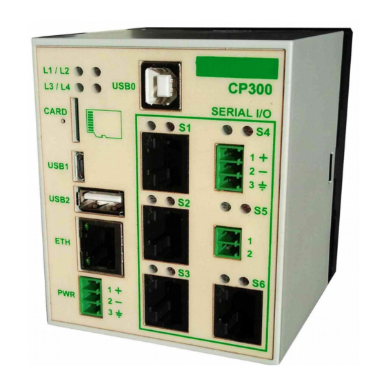
DL28 Installation and User Manual 2 Device Description DL28 is contained in plastic enclosure with 70x86x72.8mm dimensions and attachment for DIN 35 mm supporting rail. Figure 2. Back and side view of DL28 Front plate is equipped with connectors for power supply, USB peripheral devices, memory cards, Ethernet and serial connected devices, as well as indicator lights. - Page 6 DL28 Installation and User Manual DL28 has modular design, consisting of four boards: processor board, communication board, M-Bus board and base board connecting all of them into single unit. All communication ports are galvanic isolated, the same applies to power supply connector.
-
Page 7: Processor Board
DL28 Installation and User Manual 2.1 Processor Board The processor board is central part of DL28. It contains power section, processor module and headers for peripheral connectors, memory cards and Ethernet connector. Figure 5. DL28 Processor Board Block Diagram 14.05.2013. -
Page 8: Indicator Lights
LED) and network activities (lower LED). 2.1.5 Power Connector DL28 can be powered by DC sources ranging from 18 to 30V. If used power source has 24V the power consumption is up to 5W. Indicator light L1 shows presence of power voltage. Pin No. -
Page 9: Communication Board
DL28 Installation and User Manual 2.2 Communication Board Communication board features USB0 connection as well as three serial RS232/485 connections S1, S2, and S3. All of them are galvanic isolated. Figure 7. DL28 Communication Board Block Diagram 14.05.2013. -
Page 10: Serial Connector S1
DL28 Installation and User Manual 2.2.1 Serial Connector S1 RJ45 8/8 port connects external devices to UART0 processor having seven RS-232C signals. This port is used for connecting “dial-up”, GSM or other similar modem. Indicator lights located above the RJ45 show status signals for sending TXD (red LED on the right) and receiving RXD (green LED on the left). -
Page 11: Serial Connector S3
DL28 Installation and User Manual 2.2.3 Serial Connector S3 RJ45 8/8 port connects external devices to UART3 processor having four RS-232C and two RS-485 signals. This port is used for connecting devices that use asynchronous serial communications, such as personal computers (PC), programmable logic controllers (PLC) and similar devices. -
Page 12: M-Bus Board
DL28 Installation and User Manual 2.3 M-Bus Board M-Bus board serves as connection to systems and devices through standard EN1434 connector, usually being used for meters and other measuring devices. Figure 8. DL28 M-Bus Board Block Diagram 14.05.2013. -
Page 13: Serial Connector S4
DL28 Installation and User Manual 2.3.1 Serial Connector S4 3x3.5 mm connection blocks are used to link external devices to UART1 processor with M- Bus master interface according to EN1434. Up to 3 slave devices can be connected. S4 connector accepts devices with M-Bus slave output such as heath meters, water meters or gas meters. -
Page 14: Base Board
2.4 Base Board Base board serves as mechanical and electrical junction of above mentioned boards. 2.4.1 Expansion Port DL28 features expansion port for adding other input/output communication modules. In this manner basic features can be enhanced and upgraded. Pin No. Signal... -
Page 15: Dl28 Connection Ports Testing
To execute tests, personal computer should be used and connected by USB cable (A-B type). “B” end of the cable should be plugged into USB0 port on the front of DL28. Since USB0 is realised by integrated circuit FT232 (www.ftdichip.com), virtual serial port driver should be installed to PC after downloading from the web address: http://www.ftdichip.com/Drivers/VCP.htm... -
Page 16: User Login
DL28 Installation and User Manual 3.1 User Login After several seconds from starting device OS should be up and ready. Following screen shows terminal program appearance after OS start, having the prompt for user login at the bottom. Figure 10: Terminal application screen with user login prompt... -
Page 17: Ports S1
DL28 Installation and User Manual 3.2 Ports S1 ... S6 Testing After successful login serial ports S1 ... S6 can be tested by starting following system application: root@decode~$./TestPort After successful login serial ports S1 ... S6 can be tested by starting following system application: root@decode ~$ ./TestPort... -
Page 18: Test1
DL28 Installation and User Manual 3.2.1 TEST1 Following terminal screen shows execution of TestPort system application. After the TestPort is started, user is asked to connect cross-linked RJ45 serial cable to ports S1 and S2, confirming this action with y and ENTER keys. -
Page 19: Test2
DL28 Installation and User Manual 3.2.2 TEST2 For this test cross-linked RJ45 serial cable should be placed to ports S3 and S6 and confirmed by entering y and ENTER keys. Figure 12: Terminal screen output after TEST2 execution After communication testing in both ways (S3--->S6 and S6--->S3) the TEST2 is completed and application advances to TEST3 automatically. -
Page 20: Test 3
3.2.3 TEST 3 All serial cables with RJ45 connectors should be removed from DL28 device for this test. Two-wire conductors prepared earlier should be used between S4 and S5 ports. During test communication in S4--->S5 direction few unprintable characters will show in terminal window, which is normal behaviour - it shouldn't be regarded as error state or ports failure Figure 13. - Page 21 DL28 Installation and User Manual Figure 14. Terminal screen output after separate TEST2 was finished 14.05.2013.
-
Page 22: Usb Ports And Memory Card Testing
DL28 Installation and User Manual 3.3 USB Ports and Memory Card Testing USB Host port can be tested by attaching USB flash memory for instance. Following screen shows the output while attaching and later, during ejecting of USB flash memory stick. -
Page 23: Ethernet Port Testing
DL28 Installation and User Manual 3.4 Ethernet Port Testing Ethernet port can be tested by connecting DL28 with network cable to local network or personal computer and starting the web interface. Enter following IP address to your browser: http://192.168.0.67:90/ Device's web presentation shows general device info, settings and maintenance pages as well as access to uploading of application to be executed on DL28. -
Page 24: Technical Specification
DL28 Installation and User Manual 4 Technical Specification Processor board Central processor 32-bit, operating frequency 454MHz, core ARM926EJ-S Operating system Linux 2.6 Memory 256MB DDR2 SDRAM Disc storage 2GB Flash 1 x USB2.0 Hi-Speed Host, 1 x OTG Hi-Speed Ethernet...
Need help?
Do you have a question about the DL28 and is the answer not in the manual?
Questions and answers