Table of Contents
Advertisement
Quick Links
Advertisement
Table of Contents

Summary of Contents for Argus Pathfinder
- Page 1 Pathfinder 48V-1.5kW Modular Switched Mode Rectifier System 010-548-B2...
- Page 2 Argus Technologies Ltd. Visit www.argus.ca Burnaby, British Columbia. Telephone: 604 436 5900 Fax: 604 436 1233 Argus Technologies reserves the right to make changes to the products and information contained in this document without notice. ® Copyright 2008 Argus Technologies Ltd. Argus is a registered trademark of Argus Technologies Ltd.
- Page 3 19” Cabinet: 030-633-08 23” Cabinet: 030-634-08 • Spare Parts List: 010-548-G0 Factory Service Information: 048-527-10 Argus Technologies Ltd. 010-548-B2 Rev B WC Printed in Canada. © 2004 Argus Technologies Ltd. ARGUS is registered trademark of Argus Technologies Ltd. All Rights Reserved.
- Page 4 7, 15, 20 NOTE: For Pathfinder 48-1.5kW and 48V-2kW rectifiers in the same shelf (or system) of 010-548-C0 utilizing an Argus SM Series controller, set the current limit to no more than 33A (the maximum of the lower power unit). MANUAL ADDENDUM...
- Page 5 SPECIFICATIONS FOR ARGUS’ SWITCHED MODE RECTIFIER PATHFINDER 48V-1.5kW P o w e r M o d u l e O u t p u t Voltage: 42 to 60VDC Current: 0 to 33ADC Maximum Power: 1500W continuous/module @ 50 to 56VDC...
- Page 6 SPECIFICATIONS FOR ARGUS’ SWITCHED MODE RECTIFIER PATHFINDER 48V-1.5kW P o w e r M o d u l e I n p u t Voltage: 208 to 240VAC nominal 176 to 265VAC operating 90 to 312VAC extended range (derated output power or input power factor)
- Page 7 SPECIFICATIONS FOR ARGUS’ SWITCHED MODE RECTIFIER PATHFINDER 48V-1.5kW S t a n d a r d s Safety: CSA C22.2 No. 950-95 UL 1950-1995 EN 60950-1993 with Amendments 1-4, with deviation for Germany (CB Scheme). Electromagnetic Compatibility: FCC 47 CFR Part 15:1998 Class B Radiated &...
- Page 8 Hongli Industrial Area, Miaobian, Liaobu Town, Dongguan City, Guangdong Province, 523400 China Argus shall not be liable to the customer or other parties for any loss of profits, loss of use, costs for Tel: +86 755 8895 3310 Fax:...
- Page 9 SAVE THESE INSTRUCTIONS This manual contains important safety and operating instructions for the Argus Pathfinder 1.5kW & 2kW rectifier series. 1. Please read this manual thoroughly prior to use to become familiar with the rectifier’s numerous features and operating procedures. To obtain a maximum degree of safety, follow the sequences as outlined.
- Page 10 This page intentionally left blank.
-
Page 11: Table Of Contents
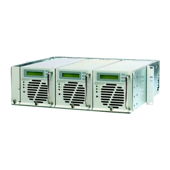
W & 2 RGUS ECHNOLOGIES ATHFINDER ONTENTS ........................1 NTRODUCTION Scope of the Manual ........................1 Product Overview ........................1 Part Numbers and List Options....................2 ................3 YSTEM EATURES LARMS AND ONTROLS Shelf Features ..........................3 Power Module Features ......................5 Module Fail Alarms ........................9 General Alarms ..........................9 .........................11 NSPECTION Packing Materials ........................11... - Page 12 Acronyms and Definitions....................... 28 IGURES Figure 1–Front perspective view of Pathfinder 19” shelf (with 1.5kw or 2kW modules) ......1 Figure 2–Front view of Pathfinder (1.5kW or 2kW) shelf (modules removed) ........... 3 Figure 3–Front perspective view of power module ..................5 Figure 4–Pathfinder LCD in Normal mode ....................
-
Page 13: Introduction
The shelf has connections for AC inputs, DC output, and various alarm/control relays. The Pathfinder rectifier system is designed to operate with the Argus SM series of system control panels via RS-485 shelf connectors for communications. This allows the user to setup, control and monitor the entire power system and ancillary components from one central, easy-to-use source. -
Page 14: Part Numbers And List Options
W & 2 RGUS ECHNOLOGIES ATHFINDER Part Numbers and List Options The Pathfinder 1.5kW or 2kW is available to order under the following part numbers and list options: Description Part Number/List Option Pathfinder 48V-1.5kW power module....................010-548-20 Pathfinder 24V-1.5kW power module....................010-549-20 Pathfinder 48V-2kW power module ....................010-558-20... -
Page 15: System Features , Alarms And Controls
ONTROLS Shelf Features The Pathfinder’s shelf contains connections for up to four rectifier power modules, AC input, DC output, sev- eral remote alarm/controls, and RS-485 communications. When the power modules are removed from the shelf, all cabling connections to the shelf are front-accessible with exception of DC outputs. DC connections are made at the rear of the shelf. - Page 16 W & 2 RGUS ECHNOLOGIES ATHFINDER 2.1.2 Shelf Alarms The rectifier shelf has alarms entitled RECTIFIER MAJOR, RECTIFIER MINOR, GENERAL ALARM, and AC FAIL. All alarms are “real time” and therefore do not latch. The minor and major alarm contacts are “fail safe”...
-
Page 17: Power Module Features
The LED indicators provide visual indication of module operational status and alarms. The indicators and as- sociated colors are as follows: 2.2.1.1 AC Mains OK This indicator illuminates when AC input to the Pathfinder is within the valid range and flashes when out of the normal range (described below). 2.2.1.2 Flashing AC Mains OK The AC Mains OK LED will flash when the input voltage is out of range, but the module will continue to op- erate down to 90VAC (current limit gradually reduces automatically to approx. - Page 18 (and releasing) causes the module to shutdown and then restart immediately — the Pathfinder interprets this as a remote signal to turn the module on. To get a reading of output current, quickly press and release the power button. The lower green LED will flash for every 20% (approx.) of maximum rated output current.
- Page 19 W & 2 RGUS ECHNOLOGIES ATHFINDER 2.2.5 True Module Fail Alarm The power modules have a “true” fail alarm. This provides a true indication of the power module's ability to source current. When the module's output current drops below 2.5% of the rated output, the Module Fail de- tection circuit is activated.
- Page 20 2.2.18 Security Access Codes An adjustable three-digit security code is programmed into the Pathfinder modules to prevent access to criti- cal control functions by unauthorized users.
-
Page 21: Module Fail Alarms
W & 2 RGUS ECHNOLOGIES ATHFINDER Module Fail Alarms The alarm conditions listed under this section signify a complete failure or shutdown of the module. 2.3.1 Remote Shutdown A module will turn off and extend an alarm when it receives a remote shutdown signal. 2.3.2 Output Fuse Open This alarm indicates the module’s output fuse has blown. - Page 22 This alarm is generated when the fan is sending an incorrect speed signal e.g. from excessive fan bearing wear. This alarm provides a warning that the fan may need to be replaced. The Pathfinder module will con- tinue to run normally during this condition.
-
Page 23: Inspection
NSPECTION Packing Materials All Argus products are shipped in rugged, double walled boxes and suspended via solid polyurethane foam inserts to minimize shock that may occur during transportation. Packaging assemblies and methods are tested to National Safe Transit Association (NSTA) standards. -
Page 24: Shelf Installation
ECHNOLOGIES ATHFINDER HELF NSTALLATION This section is provided for qualified personnel to install the Pathfinder shelf; which must be mounted in a clean and dry environment. Refer to Outline drawings 030-633-06 and 030-634-06. Safety Precautions WARNING Hazardous voltages are present at the input of power systems. The DC output... -
Page 25: Shelf Grounding , Wiring And Connections
IRING AND ONNECTIONS This chapter provides cabling details and notes on cable sizing for DC applications with respect to the Argus Pathfinder 1.5kW & 2kW. Refer to Customer Connections drawings 030-633-08 and 030-634-08. Refer to the previous (Installation) chapter for safety precautions and tools required. -
Page 26: Dc Output Connections
(i.e. +Vcable to +Vpost). If a user-provided bolt is used instead of the bolt supplied by Argus Technologies, ensure that the bolt is not too long, so that pressure will not be applied to the insulating plate behind the bolt. -
Page 27: Initial Start - Up And Checkout
W & 2 RGUS ECHNOLOGIES ATHFINDER NITIAL TART UP AND HECKOUT WARNING Confirm that the output polarity connection is correct to prevent damage to the load. Before making the final battery connection, perform the following start-up and test procedure to prevent dam- age and ensure proper system operation: 1. -
Page 28: Operation And Adjustments
LEDs to extinguish before handling. Modes Of Operation The Pathfinder’s default operation is in Float mode. The module AC LED and ON LED is illuminated and various identification messages are displayed on the (optional) LCD. See the figure below for a sample screen. -
Page 29: Menu Structure
ATHFINDER Menu Structure On the Pathfinder version with no LCD, the menu interface is only available remotely through the SM series system controller or a computer terminal emulation program (refer to these product manuals for more infor- mation on the user interface). -
Page 30: Figure 5-Pathfinder Menu Tree
LOC LOCK DISABLE BACKLIGHT TIMEOT RETURN TEMP DISPL DEG C/F EXIT PROTECTED ADJUST RETURN EXIT REMOTE ACCESS REMOTE ADJUST MODULE ID# BAUD RATE RETURN EXIT MANUAL TEST BT VOLT BT DUR BT TEST = RETURN EXIT Figure 5–Pathfinder menu tree 010-548-C0 R... - Page 31 This function allows the user to adjust the slope percentage. Output slope is a method of load sharing which operates by altering the output voltage regulation of the Pathfinder module. Output slope is factory default at 1% and it is recommended to leave it at that value. Slope settings must be the same for all rectifiers in that system and should be 1%.
- Page 32 The Module Fail LED will turn on and the Module Fail Relay will de-energize. The O/P HV SHUTDOWN and MODULE FAIL alarms will be extended remotely. The over voltage shutdown feature of the Pathfinder is selective and operates at 5% higher voltage in a less than 2.5% load condition.
- Page 33 Status screen to be transmitted. Access is not allowed to the Adjustments and Test Mode menus; accessing these menus causes the Pathfinder to respond with "ADJUST LOCKOUT". Access must be allowed to the Remote Communications menu. The Pathfinder security code is required to make any changes.
-
Page 34: Miscellaneous Defaults/Adjustments/Controls
W & 2 RGUS ECHNOLOGIES ATHFINDER 7.5.3.4 Baud Rate This control allows the user to set the baud rate for communications between the module and a remote site. 7.5.4 Test Mode This menu category enables operators to check the functionality of the output voltage. To activate, scroll to the relevant menu item and press the ENTER button or use the SM controller. -
Page 35: Factory Defaults And Ranges
W & 2 RGUS ECHNOLOGIES ATHFINDER Factory Defaults and Ranges Submenu Item Programmable Range Default Setting Default Setting 24VDC Systems 48VDC Systems Float Voltage 24.0 – 29.0V (24V) 27.0V 48.0 – 58.0V (48V) 54.0V Equalize Voltage 25.0 – 30.0V (24V) 27.5V 50.0 –... -
Page 36: Remote Communications
ATHFINDER EMOTE OMMUNICATIONS The Pathfinder rectifier system is optimized for remote communications. It can be controlled, monitored and tested via the SM series intelligent supervisory panel or via an ASCII display terminal. Multiple Shelf Connections (RS-485) Rectifier shelves can be daisy-chained together via the RS-485 interface. Refer to the customer connection drawings 030-633-08 for locations and pinout details of the serial communications interface (SCI) connectors. -
Page 37: Communications Using A Pc/Terminal
Before connecting the host equipment, ensure the communications access parameters – including default baud rate of your terminal – is set to match the Pathfinder module. The default parameters are set to 8 data bits, 1 stop bit, and no parity. -
Page 38: Maintenance And Service
Refer to the Specifications section at the front of this manual for replacement parts. Maintenance Although very little maintenance is required with Argus rectifier systems, routine checks and adjustments are recommended to ensure optimum performance. Repairs should be done by qualified service personnel. - Page 39 W & 2 RGUS ECHNOLOGIES ATHFINDER 9.2.3 Fuse Replacement 9.2.3.1 AC Fuse Replacement 1. Shut off the unit and remove the screw that secures the power module to the shelf. 2. Slide the module 10 cm (4”) out of the shelf and wait two minutes for module capacitors to discharge.
-
Page 40: Argus Conventions
“-20” Main Assembly Argus uses an eight-digit part numbering system for all components and sub assemblies. Each part is covered by its own unique number. Due to the quantity, categories will not be listed within this manual. 10.2 Acronyms and Definitions... - Page 41 WIRED DIRECTLY TO EACH MODULE NOT SHOWN AND RS-485 CONNECTORS TERMINAL BLOCK 22.31 566.6 THESE DESIGNS AND SPECIFICATIONS ARE THE PROPERTY OF ARGUS TECHNOLOGIES AND SHALL NOT BE COPIED OR USED FOR MANUFACTURING WITHOUT ITS WRITTEN CONSENT. 23.00 584.1 DESIGN 1999/11 MATERIAL...
- Page 42 LIST 25 - FLUSH MOUNT TOP VIEW FOR 23" RACK c 2000 ARGUS TECHNOLOGIES THESE DESIGNS AND SPECIFICATIONS ARE THE PROPERTY OF ARGUS TECHNOLOGIES AND SHALL NOT BE COPIED OR USED FOR MANUFACTURING WITHOUT ITS WRITTEN CONSENT. DESIGN 1999/11 MATERIAL...
- Page 43 CUSTOMER DC OUTPUT CONNECTIONS 3/8" - 16 NC BOLTS WITH 1" [25mm] SPACING (COVER REMOVED) THESE DESIGNS AND SPECIFICATIONS ARE THE PROPERTY OF ARGUS TECHNOLOGIES AND SHALL NOT BE COPIED OR USED FOR MANUFACTURING WITHOUT ITS WRITTEN CONSENT. DESIGN 1999/11...
- Page 44 (MODULES REMOVED) LIST 84: CABINET AC INPUT CAN BE WIRED TO THESE DESIGNS AND SPECIFICATIONS ARE THE PROPERTY OF ARGUS TECHNOLOGIES AND SHALL NOT BE COPIED OR USED 2X 2 POSITION TERMINAL BLOCKS FOR MANUFACTURING WITHOUT ITS WRITTEN CONSENT. 2000/05...
- Page 45 LIST 23 6" OFFSET 13.63 346.1 13.18 334.8 11.97 304.1 6.00 152.4 THESE DESIGNS AND SPECIFICATIONS ARE THE PROPERTY OF ARGUS TECHNOLOGIES AND SHALL NOT BE COPIED OR USED FOR MANUFACTURING WITHOUT ITS WRITTEN CONSENT. 2000/05 MATERIAL DESIGN 2000/07 DRAWN...
- Page 46 1" CONDUIT FITTING CUSTOMER DC OUTPUT CONNECTIONS 3/8"-16 NC BOLTS WITH 1" [25mm] SPACING (COVER REMOVED) THESE DESIGNS AND SPECIFICATIONS ARE THE PROPERTY OF ARGUS TECHNOLOGIES AND SHALL NOT BE COPIED OR USED FOR MANUFACTURING WITHOUT ITS WRITTEN CONSENT. 2000/05 MATERIAL DESIGN...
- Page 49 POWER MODULE, APPROVED: ______________ PATHFINDER 48V-1.5KW ISSUED: ______________ ITEM PART NO. REV DESCRIPTIONCIRCUIT DESIGNATION OR REMARKS List 0; On Site: 747-136-20 Assy, Module,Cooling Fan, Pathfinder Dwg(A) 747-136-04 48V-1.5KW 707-254-20 Assy, PCB, Transient Protection (A1) List 0 Pathfinder 1.5KW 460-042-10 Fu,1/4"x1-1/4",15A 250V,Fast...
- Page 50 Technical support staff are available for answering general questions related to installation, operation Argus Technologies Ltd. ATTN: RMA Returns and maintenance of Argus products. In Canada and the USA, call Argus toll free 7:30 am to 5:00 pm 7033 Antrim Avenue Pacific Standard Time at:...
Need help?
Do you have a question about the Pathfinder and is the answer not in the manual?
Questions and answers