Table of Contents
Advertisement
Quick Links
Installation and Operating Manual
(Translation of the original installation and operating manual)
T...
Turbo Coupling with Constant Fill
including design as per ATEX directives:
Directive 94/9/EC (valid until April 19, 2016), Directive 2014/34/EU (valid from April 20, 2016)
Version 10 , 2016-01-11
3626-011000 en, Protection Class 0: public
1)
Serial No.
2)
Coupling type
Year of manufacture
Mass (weight)
Power transmission
Input speed
Operating fluid
Filling volume
Number of screws z
Nominal response temperature of
fusible plugs
Connecting coupling type
Sound pressure level L
Installation position
Drive via
1)
Please indicate the serial number in any correspondence ( Chapter 18).
2)
T...: oil
/
TW...: water.
3)
Determine and record the number of screws z ( Chapter 10.1).
Please consult Voith Turbo in case that the data on the cover sheet are incomplete.
mineral oil
water
3)
PA,1m
horizontal
vertical
outer wheel
inner wheel
kg
kW
rpm
3
dm
(liters)
°C
dB
Advertisement
Table of Contents

Related Manuals for Voith TN Series


Summary of Contents for Voith TN Series
- Page 1 Please indicate the serial number in any correspondence ( Chapter 18). T...: oil TW...: water. Determine and record the number of screws z ( Chapter 10.1). Please consult Voith Turbo in case that the data on the cover sheet are incomplete.
- Page 2 Turbo Coupling with Constant Fill Contact Contact Voith Turbo GmbH & Co. KG Division Mining & Metals Voithstr. 1 74564 Crailsheim, GERMANY Tel. + 49 7951 32 409 Fax + 49 7951 32 480 startup.components@voith.com www.voith.com/fluid-coupling 3626-011000 en This document describes the state of design of the product at the time of the editorial deadline on 2016-01-11.
-
Page 3: Table Of Contents
Turbo Coupling with Constant Fill Contents Contents Voith Turbo Coupling with Constant Fill Function Type designation Constructional examples 1.3.1 Connecting coupling on the input side 1.3.2 Connecting coupling on the output side Technical Data Tightening Torques Set screws and fixing bolts... - Page 4 Turbo Coupling with Constant Fill Contents Qualification of staff 6.10 Product monitoring Transport and Storage As delivered condition Scope of supply Transport Lifting Storage / Packing / Preservation 7.5.1 Storage of turbo coupling 7.5.2 Storage of flexible element Installation and Alignment Tools Preparation 8.2.1...
- Page 5 Turbo Coupling with Constant Fill Contents Proposed operating fluids for special requirements Requirements to be fulfilled by the operating fluid 'water' 9.3.1 Usable operating fluids 9.3.2 Water used as operating fluid for turbo couplings with centrifugal valves (types TW…F…) Filling, Filling Check and Draining 10.1 Filling the turbo coupling 10.1.1...
- Page 6 Turbo Coupling with Constant Fill Contents 13.4 Fusible plugs 13.4.1 Fusible plugs in turbo couplings not suitable for use in potentially explosive atmospheres 13.4.2 Fusible plugs in turbo couplings suitable for use in potentially explosive atmospheres Assembly Check-, Commissioning and Maintenance Report 14.1 Assembly check report 14.2...
- Page 7 Turbo Coupling with Constant Fill Contents Spare Parts Information 20.1 Components overview - Voith turbo coupling 154 – 1150 20.2 Spare parts for Voith turbo coupling 154 – 274 20.3 Spare parts for Voith turbo coupling 366 – 1150 20.4 Spare parts for connecting coupling 20.4.1...
-
Page 8: Voith Turbo Coupling With Constant Fill
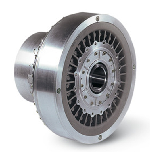
Shell Fig. 1 The Voith turbo coupling is a hydrodynamic coupling working to the Föttinger principle. Its main elements consist of two blade wheels - the pump impeller and the turbine wheel - enclosed by a shell. Both wheels are provided with bearings relative to each other. - Page 9 Turbo Coupling with Constant Fill Voith Turbo Coupling with Constant Fill Three conditions are to be considered with regard to the coupling function: Standstill The whole operating fluid rests in the coupling. Fig. 2 Starting condition The pump impeller accelerates...
-
Page 10: Type Designation
Material "no code letter": Silumin ferrous material Operating fluid "no code letter": mineral oil water (please consult Voith regarding anti-freezing agent) Delay chamber "no code letter": without delay chamber with delay chamber with enlarged delay chamber Draining of delay chamber "no code letter":... -
Page 11: Constructional Examples
Turbo Coupling with Constant Fill Voith Turbo Coupling with Constant Fill 1.3 Constructional examples 1.3.1 Connecting coupling on the input side Type T (basic type): Type TV: Fig. 5 Fig. 6 Type TVVS: Type TVV: Fig. 7 Fig. 8 Type DT: Type DTV: Fig. -
Page 12: Connecting Coupling On The Output Side
Turbo Coupling with Constant Fill Voith Turbo Coupling with Constant Fill 1.3.2 Connecting coupling on the output side Type TN (basic type): Fig. 11 Type TVN: Fig. 12 Type TVVN: Design 1 __ _ __ _ __ Design 2 Fig. 13... -
Page 13: Technical Data
°C or deviating) Temperature monitoring for pre-warning for pre-warning BTS-Ex for limitation of max. surface temperature for Voith turbo couplings acc. to ATEX Directive. Maximum permissible temperature of turbo coupling when switching on the motor: °C Nominal response temperature of temperature monitoring °C... - Page 14 Turbo Coupling with Constant Fill Technical Data Additional information/data required for use in potentially explosive atmos- pheres:...
-
Page 15: Tightening Torques
Turbo Coupling with Constant Fill Tightening Torques 3 Tightening Torques NOTICE Damage to property The turbo coupling may be damaged by incorrectly tightened screws. • Tighten all screws using a torque-adjustable torque wrench! Blind screw, Filler plug, Fusible plug, item 0394 item 0390 item 0260 Nozzle screw,... -
Page 16: Set Screws And Fixing Bolts
Turbo Coupling with Constant Fill Tightening Torques 3.1 Set screws and fixing bolts Tightening torque in Nm Thread Set screw, item 1845 Fixing bolt, 1350 2350 3750 item 0050 Table 2 The tightening torques for set screws apply to property classes as per EN ISO 898-5. The tightening torques for fixing bolts apply to screws with property class 8.8 or higher (as per EN ISO 898-1), oil-moistened and relevant shaft journal material. -
Page 17: Fastening Screws
Turbo Coupling with Constant Fill Tightening Torques 3.3 Fastening screws Tightening torque in Nm (dimension of thread) Coupling Fastening Fastening Socket head Hex. screw, size screw, screw, screw, EPK, item 0780, item 1660 Nor-Mex G, item 1870 item 1830 item 1816 (M6) (M8) (M12) -
Page 18: Declarations Of Manufacturer
The technical documentation for Voith products is so comprehensive that they may be installed reliably into machinery or incomplete machinery. Safe operation of the complete machinery with regard to Voith products is also ensured at a later date when observing this documentation. -
Page 19: Conformity Declaration
EC Conformity Declaration as per Directive 94/9/EC (valid until April 19, 2016), EU Conformity Declaration as per Directive 2014/34/EU (valid from April 20, 2016) The manufacturer Voith Turbo GmbH & Co. KG, Voithstraße 1, 74564 Crailsheim / Germany hereby declares that the machinery described below: Description T…... -
Page 20: User Information
Installation and/or use of non-original spare parts may negatively change the mechanical properties of the Voith turbo coupling and thus have an adverse impact on safety. Voith is not liable for any damages resulting from the use of non-original spare parts. only appropriate... - Page 21 Offenders will be held liable for the payment of damages. All rights reserved in case a patent is granted, or a utility model or design is registered. Voith Turbo reserves the right for modifications.
-
Page 22: Safety
Turbo Coupling with Constant Fill Safety 6 Safety 6.1 Safety information Safety information indicating the descriptions and symbols as described in the following are used in the operating manual. 6.1.1 Structure of safety information DANGER WORD Hazard consequences Source of hazard •... -
Page 23: Definition Of Safety Symbols
Turbo Coupling with Constant Fill Safety 6.1.2 Definition of safety symbols Symbol Definition Danger of explosion Marking with the Ex-symbol indicates possible hazards which have to be observed for the use in potentially explosive atmospheres. Table 6 6.2 Intended use The turbo coupling with constant fill is provided to transmit the torque from the drive motor to the driven machine. -
Page 24: Unintended Use
• Modifications, attachments or conversions on the turbo coupling are only allowed with the approval of Voith Turbo GmbH & Co. KG, Crailsheim. 6.5 General information as to dangerous situations For all work performed on the turbo coupling, please observe the local... - Page 25 Turbo Coupling with Constant Fill Safety Hot surfaces: WARNING Risk of burning The turbo coupling gets warm during operation. • Please provide a guard for protection against contact with the turbo coupling! However, ventilation of the turbo coupling must not be impaired. NOTICE Damage to property Thermal distorsion or tensions if the warm turbo coupling is cooled down by...
- Page 26 Turbo Coupling with Constant Fill Safety Electric shock: DANGER Electric shock On account of incorrectly mounted or incorrectly connected electrical components, and disconnected electric connections, persons could get an electric shock and be severely injured, possibly with fatal consequences. Incorrectly mounted or incorrectly connected electrical components and disconnected electric connections may cause damages to the machine.
- Page 27 Turbo Coupling with Constant Fill Safety Extreme ambient temperatures: Ambient WARNING temperature Chapter 2 Risk of personal injuries and damage to property Extreme ambient temperatures may result in thermal overload of the turbo coupling, thus causing the fusible plugs to melt and seriously injure any persons in their immediate surroundings, and to cause damage to the turbo coupling.
- Page 28 Turbo Coupling with Constant Fill Safety WARNING Fire hazard After the fusible plugs responded, spraying off oil may ignite on hot surfaces causing fire, as well as releasing toxic gases and vapor. • Make sure that spraying off operating fluid cannot get into contact with hot machine parts, heaters, sparks or open flames.
-
Page 29: Remaining Risks
These values describe a permissible working point for the stationary operation of the turbo coupling. NOTICE Damage to property Deviations from the permissible working point cause damage the turbo coupling. • Voith Turbo's approval is required for a stationary operation of the turbo coupling at a different working point. - Page 30 Turbo Coupling with Constant Fill Safety Operating fluid: NOTICE Damage to property Too little filling results in thermal overload of the turbo coupling, and in case of too much filling, the turbo coupling may be damaged by internal pressure. • Operate the turbo coupling only with the filling quantity stated on the cover sheet of this manual.
- Page 31 Damage due to under temperature The turbo coupling may be damaged by under temperature. • Please consult Voith Turbo if the turbo coupling shall be used at ambient temperatures • below -25 °C for operating fluid 'oil' •...
- Page 32 Turbo Coupling with Constant Fill Safety Monitoring devices: Monitoring devices NOTICE Chapter 19 Damage to property Damage to turbo coupling due to monitoring devices not ready for service. • Check whether existing monitoring devices are in a state ready for service. •...
- Page 33 • the driven machine blocks • the driven machine is loaded excessively during nominal operation and/or during start-up. Please consult Voith Turbo in case of unforeseeable turbo coupling overload. Connecting Connecting couplings: couplings Chapter 20.4 Connecting couplings of types EPK, ERK:...
-
Page 34: Qualification Of Staff
Turbo Coupling with Constant Fill Safety 6.9 Qualification of staff Only qualified and authorized professional staff are allowed to perform work, such as transportation, storage, installation, electrical connection, commissioning, operation, maintenance, servicing and repair. Qualified professional staff in the sense of this operating manual are persons who are familiar with transportation, storage, installation, electrical connection, commissioning, maintenance, servicing and repair and who have got the necessary qualifications relevant to their job performed. -
Page 35: Transport And Storage
Turbo Coupling with Constant Fill Transport and Storage 7 Transport and Storage 7.1 As delivered condition Packaging – The turbo coupling is delivered in ready-mounted condition. Chapter 7.5 – The turbo coupling is not filled. If the scope of supply includes the operating fluid, it will be delivered in a separate container. -
Page 36: Transport
Turbo Coupling with Constant Fill Transport and Storage 7.3 Transport WARNING Explosion hazard For turbo couplings with housings made of aluminum alloys, there can be the risk of explosion when being transported in / through explosive atmospheres. • In potentially explosive atmospheres it is only allowed to transport the turbo coupling in suitable packing. -
Page 37: Lifting
Turbo Coupling with Constant Fill Transport and Storage 7.4 Lifting Lifting appliances, load carrying attachments, lifting points For weight of the Observe the turbo coupling weight! turbo coupling cover sheet. Weights of over Lifting appliances (e.g. crane, high-lift truck), slings (ropes, chains, etc.) and lifting 100 kg will be points (swivels, thread size as for items 1830 or 0780, ... - Page 38 Turbo Coupling with Constant Fill Transport and Storage NOTICE Personal injury and damage to property Improper fixing and lifting of the turbo coupling may cause personal injury and damage to property • It is only allowed to lift the turbo coupling at the lifting points provided for this purpose (see the following pictures).
- Page 39 Turbo Coupling with Constant Fill Transport and Storage WARNING Risk of injury Danger to life and risk of injury caused by falling load, tilting or sliding of the turbo coupling. • Slings (ropes, chains, etc.) must not be slung around the turbo coupling for lifting.
- Page 40 Turbo Coupling with Constant Fill Transport and Storage WARNING Risk of crushing Incorrect handling of the turbo coupling may cause bruising of upper and lower limbs and seriously injure persons. • Always use at least 2 slings (ropes, chains, etc.) for fixing. •...
- Page 41 Turbo Coupling with Constant Fill Transport and Storage • Align the turbo coupling horizontally using the two lifting appliances. Fig. 19 • Carefully set the turbo coupling down on a wooden board / pallet, and secure it against tilting. The turbo coupling has been turned.
-
Page 42: Storage / Packing / Preservation
7.5 Storage / Packing / Preservation 7.5.1 Storage of turbo coupling As delivered condition The as delivered condition of the Voith Turbo Couplings depends on the mode of transport and the storage period: Condition No. 1 represents the delivered standard, for deviations, ordering documents. - Page 43 Turbo Coupling with Constant Fill Transport and Storage External preservation / re-preservation Renew the external preservation according to the allowable storage period. Spray bright metal parts (hub bores, brake disks, etc.) with Houghton Ensis DWG2462. Internal preservation / re-preservation: Renew the internal preservation annually (for Condition No. 4: every 2 years). Wet the turbo coupling inside with an oil selected from the selection list.
-
Page 44: Storage Of Flexible Element
Turbo Coupling with Constant Fill Transport and Storage NOTICE Damage to property Danger of frost • When storing turbo couplings of type "TW" below 1°C, drain the water. • Remove the flexible element (item 1820) prior to cleaning the coupling components and applying the long-term preservation! 7.5.2 Storage of flexible element... -
Page 45: Installation And Alignment
Turbo Coupling with Constant Fill Installation and Alignment 8 Installation and Alignment WARNING Risk of injury Please observe, in particular, Chapter 6 (Safety) when working on the turbo coupling! 8.1 Tools WARNING Explosion hazard There is the risk of explosion when using unsuitable tools. •... -
Page 46: Preparation
Check the length of fixing bolt if the length of the shaft journal, on which the turbo stamped on the turbo coupling. coupling is mounted, was changed or not indicated to Voith Turbo. • Clean fitting surfaces on shaft journals and hubs using emery cloth. -
Page 47: Keys
Turbo Coupling with Constant Fill Installation and Alignment Proposed lubricants: Producer Designation Note Dow Corning Molykote G-N Plus Paste Molykote G-Rapid Plus Paste Molykote TP 42 Fuchs Gleitmo 815 Liqui Moly LM 48 Montagepaste Dow Corning Molykote D 321 R Anti-Friction Coating Hazardous substance! Observe the data sheet for hazardous substances! -
Page 48: Mounting Of Basic Type T Turbo Coupling
Turbo Coupling with Constant Fill Installation and Alignment – For coupling hubs of sizes 154, 206 and 274 with a key or half-key convention, a compensation groove can be provided opposite for balancing of unbalance. – For coupling hubs with a key and full-key convention, an identical compensation groove is provided opposite for balancing of unbalance. - Page 49 Turbo Coupling with Constant Fill Installation and Alignment NOTICE Damage to property The use of unsuitable working means or methods may cause damage to property. • Only use tools suitable for mounting: - Mounting and removal device (from coupling size 274) available as accessory •...
- Page 50 Turbo Coupling with Constant Fill Installation and Alignment WARNING Risk of burning The surface is hot due to getting warm. • Do not touch the hub. • Nabe auf ca. 80 °C vorsichtig erwärmen (erleichtert das Aufziehen). • Mount the turbo coupling on the relevant shaft journal. •...
- Page 51 Turbo Coupling with Constant Fill Installation and Alignment NOTICE Damage to property The flexible connecting coupling hub has to be secured axially! • Usually this is achieved by means of a set screw pressing on the key. • Axial butting to a shaft collar and securing by means of a holding disk and fixing bolt are also possible.
-
Page 52: Mounting Device
Turbo Coupling with Constant Fill Installation and Alignment 8.3.2 Mounting device Mounting device for the basic type T turbo coupling is available at Voith Turbo. Fig. 23 Mounting spindle Total length Original holding disk Length of spacer tube Coupling hub... -
Page 53: Mounting Of Basic Type Tn Turbo Coupling
Turbo Coupling with Constant Fill Installation and Alignment 8.4 Mounting of basic type TN turbo coupling Outer wheel drive: The primary coupling flange is mounted on the motor shaft. Then the turbo coupling is connected with the primary coupling flange and coupled to the driven machine shaft through a flexible connecting coupling. - Page 54 Turbo Coupling with Constant Fill Installation and Alignment Connecting coupling Fastening screw, item 0780 Set screw Primary coupling flange 1 Set screw Design 1 ___ _ ___ _ ___ Design 2 Set screw Primary coupling flange 2 Fig. 24 WARNING Risk of burning The surface is hot due to getting warm.
- Page 55 Turbo Coupling with Constant Fill Installation and Alignment Correct! Incorrect! 1. No gap! Do not cant! 2. Bolt! Fig. 25 • Tightening torque Fix the turbo coupling to the primary coupling flange using the relevant bolts (item Chapter 3.3 0780).
-
Page 56: Alignment
The flexible connecting coupling absorbs these deviations of position. 8.5.1 Connecting coupling on the input side (outer wheel drive) The following connecting couplings are available at Voith Turbo for basic type T turbo couplings: Flexible roller coupling Flexible pad coupling Type ERK: Type EPK: Fig. - Page 57 Turbo Coupling with Constant Fill Installation and Alignment Flexible element coupling Flexible element coupling Type EEK-M: Type EEK-E: Fig. 28 Fig. 29 Flexible cam coupling Flexible cam coupling Type ENK-SX: Type ENK-SV: Fig. 30 Fig. 31...
-
Page 58: Connecting Coupling On The Output Side (Outer Wheel Drive)
Turbo Coupling with Constant Fill Installation and Alignment 8.5.2 Connecting coupling on the output side (outer wheel drive) Connecting coupling available at Voith Turbo for basic type TN turbo couplings: Flexible connecting coupling Type Nor-Mex G: Fig. 32 8.5.3 Laid lengths and type allocations... - Page 59 Turbo Coupling with Constant Fill Installation and Alignment Laid lengths L for flexible connecting couplings, as shown in Chapters 8.5.1 or 8.5.2: Laid lengths L in mm Coupling ERK with Nor- size and EEK-E EEK-M ENK-SX ENK-SV coupling Mex G type 154 T…...
-
Page 60: Displacement Values
Turbo Coupling with Constant Fill Installation and Alignment 8.5.4 Displacement values WARNING Explosion hazard Explosion hazard due to damage to the material caused by excessive misalignments. • Keep within the permissible tolerances for true radial and axial running during all operating conditions. •... -
Page 61: Alignment
Turbo Coupling with Constant Fill Installation and Alignment NOTICE Damage to property Overspeed Maximum • It is mandatory to observe the maximum permissible speed! permissible speed cover sheet Maximum permissible displacement values for radial and axial deflection of dial gauge. - Page 62 Turbo Coupling with Constant Fill Installation and Alignment Fig. 33 Fig. 34 Fig. 35 Fig. 36 • Mount the turbo coupling. • Align the input and output shaft with each other according to the above schematic sketch (above). The displacement values of Chapter 8.5.4 apply. •...
-
Page 63: Operating Fluids
• Unsuitable operating fluids may damage the turbo coupling permanently! • Consult Voith Turbo if you want to use an operating fluid not mentioned. NOTICE Environmental pollution Operating fluids are detrimental to health and may pollute the environment. •... -
Page 64: Requirements To Be Fulfilled By The Operating Fluid 'Mineral Oil
*) In special cases, ISO VG 10 - 46 can be used 9.1.2 Operating temperature frequently above 100 °C FPM/FKM is recommended as sealing material; when selecting the mineral oil, ensure that it provides excellent oxidation resistance. This is ensured if original Voith sealings are used. -
Page 65: Proposed Operating Fluids
Turbo Coupling with Constant Fill Operating fluids 9.1.3 Proposed operating fluids Producer Designation Pour Flash Fire Class point point point Test in °C in °C in °C fulfilled Addinol Hydraulic oil HLP 32 Agip Agip Oso 32 Agip Blasia 32 Avia Avia Fluid RSL 32 Gear RSX 32 S... -
Page 66: Proposed Operating Fluids For Special Requirements
Turbo Coupling with Constant Fill Operating fluids 9.2 Proposed operating fluids for special requirements Operating fluid suitable for the use in the food industry Producer Designation Pour point Flash point Class in °C in °C Klüber Summit HySyn FG 32 >230 Table 14 Note:... -
Page 67: Requirements To Be Fulfilled By The Operating Fluid 'Water
Turbo Coupling with Constant Fill Operating fluids 9.3 Requirements to be fulfilled by the operating fluid 'water' Requirement to Sealing compatibility NBR (Nitril-Butadien caoutchouc) ph value 5…8 The water used should – to the greatest possible extent, be free from solid matters, –... -
Page 68: Water Used As Operating Fluid For Turbo Couplings With Centrifugal Valves (Types Tw
Turbo Coupling with Constant Fill Operating fluids 9.3.2 Water used as operating fluid for turbo couplings with centrifugal valves (types TW…F…) NOTICE Damage to property Insuffucient lubrication of turbo couplings with centrifucal valve (types TV...F...). • Observe the respective type! •... - Page 69 Turbo Coupling with Constant Fill Operating fluids Proposed greases: Producer Designation Avia Lithoplex 2 EP Energrease HTG 2 Castrol Tribol GR 4020/220-2 PD Tribol GR 4747/220-2 HT ExxonMobil Mobilith SHC 220 Fuchs Renolit CXI 2 Klüber Petamo GHY 133N Shell Gadus S2 V220 2 Gadus S5 V220 2 Total...
-
Page 70: Filling, Filling Check And Draining
Turbo Coupling with Constant Fill Filling, Filling Check and Draining 10 Filling, Filling Check and Draining The quantity and type of operating fluid used substantially determines the performance of the turbo coupling. – A too high quantity stresses the drive motor more on start-up and results in a higher stall torque. -
Page 71: Filling The Turbo Coupling
Turbo Coupling with Constant Fill Filling, Filling Check and Draining Impurities in the operating fluid cause higher wear on the coupling as well as damages to bearings so that explosion protection can no longer be guaranteed. – Make sure that any containers, funnels, filling tubes, etc. used for filling the coupling, are clean. - Page 72 Turbo Coupling with Constant Fill Filling, Filling Check and Draining • Amount of grease For turbo couplings with centrifugal valves (type TW...F...), fill in the specified Chapter 9.3.2 amount of grease into the working chamber of the turbo coupling. •...
-
Page 73: How To Fill Turbo Couplings Installed In Vertical Position, Inclination
Fit the level check device to the connection provided for this purpose. ( device is available at schematic sketch above). Voith Turbo as • accessory for Provide the level mark on the turbo coupling or protective cover for later level couplings from checks. -
Page 74: Level Check
Turbo Coupling with Constant Fill Filling, Filling Check and Draining 10.2 Level check You will find the filling volume on the cover sheet of this operating manual. 10.2.1 Level check for turbo couplings installed in horizontal position SAFETY INFORMATION From size 366, turbo couplings are equipped with a sight glass in the outer wheel. -
Page 75: Level Check For Turbo Couplings Installed In Vertical Position
SAFETY INFORMATION The level of turbo couplings from size 366 is checked using a level check device. This level check device is available as accessory at Voith Turbo ( schematic sketch, Chapter 10.1.2). Turbo couplings up to size 274 need to be drained to check the filling, and then be re-filled. -
Page 76: Draining Of Turbo Couplings Without Delay Chamber Installed In Horizontal Position
Turbo Coupling with Constant Fill Filling, Filling Check and Draining 10.3.1 Draining of turbo couplings without delay chamber installed in horizontal position • Put a catch pan underneath. • Turn the turbo coupling until one fusible plug it at the bottom. •... -
Page 77: How To Drain Turbo Couplings Installed In Vertical Position
Turbo Coupling with Constant Fill Filling, Filling Check and Draining • Turn the turbo coupling until the opening of the fusible plug is at the bottom. • The remaining operating fluid flows out from the working chamber of the turbo coupling. -
Page 78: Commissioning
A perforated sheet with 65% hole cross section enclosing the coupling on all sides does not reduce the ventilation (consult Voith Turbo, if necessary). • guarantee safety distances to prevent hazard zones from being reached (DIN EN ISO 13857). - Page 79 Turbo Coupling with Constant Fill Commissioning WARNING Gefahr durch hineinziehen Slack clothing, long hair, necklaces, rings or loose parts may get caught and be drawn in or wound up causing serious injuries or damage to the turbo coupling and the environment. •...
- Page 80 Turbo Coupling with Constant Fill Commissioning Information with regard to commissioning – The turbo coupling may be used for any direction of rotation. – The direction of rotation of the driven machine may be specified! The direction of rotation of the motor must be in accordance with the specified direction of rotation of the driven machine! –...
-
Page 81: Operation
Turbo Coupling with Constant Fill Operation 12 Operation WARNING Risk of injury Please observe, in particular, Chapter 6 (Safety) when working on the turbo coupling! • An operation presupposes the successful commissioning according to Chapter 11. Information with regard to operation NOTICE Damage to property Never operate the turbo coupling without operating fluid. -
Page 82: Maintenance, Servicing
Turbo Coupling with Constant Fill Maintenance, Servicing 13 Maintenance, Servicing Definition of the maintenance work described in the following (as per IEC 60079): Maintenance and Servicing: A combination of all activities conducted in order to maintain an object in a condition or to re-store it to such a condition which meets the requirements of the respective specification and ensures performance of the required functions. - Page 83 Turbo Coupling with Constant Fill Maintenance, Servicing WARNING Risk of injury Please observe, in particular, Chapter 6 (Safety) when working on the turbo coupling! • Please always keep access paths free to the turbo coupling! Qualification – Skilled and authorized persons only are allowed to carry out maintenance and ...
- Page 84 Voith. In case of noise, vibrations Have the cause determined and eliminated by skilled persons authorized by Voith. In case of impurities Cleaning ( Chapter 13.1). After contact with materials against which NBR...
-
Page 85: Outside Cleaning
Turbo Coupling with Constant Fill Maintenance, Servicing For explosion-proof turbo couplings, the following maintenance work needs to be carried out in addition: Maintenance intervals Maintenance work In case of impurities or dusting: Cleaning ( Chapter 13.1). Clean the turbo coupling when used in potentially explosive atmospheres in regular intervals. -
Page 86: Flexible Connecting Coupling
Turbo Coupling with Constant Fill Maintenance, Servicing 13.2 Flexible connecting coupling 13.2.1 Checking the flexible element for wear Connecting coupling of type Connecting coupling of type ERK, EEK, EPK, Nor-Mex G: ENK: Fig. 40 Fig. 39 • Turn the turbo coupling until the flexible element touches without load. •... - Page 87 Turbo Coupling with Constant Fill Maintenance, Servicing Permissible reference diamentions of the flexible connecting couplings in mm Coupling EEK-E ENK-SX Nor-Mex G size EEK-M ENK-SV < 6 < 6 > 13.5 < 8 < 8 > 14 < 12 < 8 >...
-
Page 88: Maintenance Intervals
Turbo Coupling with Constant Fill Maintenance, Servicing 13.2.2 Maintenance intervals If, based on the previous wear, wear of 80% of the table value is to be expected until the next check is performed, replace the flexible element or shorten the maintenance intervals accordingly. -
Page 89: Replacement Of Bearings / Re-Lubrication
SAFETY INFORMATION Replacement interval On the occasion of an overhaul of the turbo couplings, have the bearings of ball and roller replaced / re-lubricated by skilled persons authorized by Voith. bearings Chapter 2 13.4 Fusible plugs – The fusible plugs protect the turbo coupling against damage due to thermal overload. -
Page 90: Fusible Plugs In Turbo Couplings Not Suitable For Use In Potentially Explosive Atmospheres
Turbo Coupling with Constant Fill Maintenance, Servicing SAFETY INFORMATION Switching elements, unbalance • There is a MTS and/or BTS switching element or a blind screw opposite the sight glass (position is marked by an arrow). • Insert a weight-tolerated BTM blind screw opposite the BTM switching element. - Page 91 Turbo Coupling with Constant Fill Maintenance, Servicing Number and position of fusible plugs, blind screws and switching elements for outer wheel drive (inner wheel drive): Shell (item 0190) Coupling size Fusible plug Blind MTS-, BTS- and type screw switching Item 0260 Item 0265 element 154 T…...
-
Page 92: Fusible Plugs In Turbo Couplings Suitable For Use In Potentially Explosive Atmospheres
If a brake is used, select the position of the fusible plugs so that they do not spray onto the brake. • This needs to be checked. In case of any deviation, please consult Voith Turbo. SAFETY INFORMATION Thermal monitoring devices •... - Page 93 Turbo Coupling with Constant Fill Maintenance, Servicing Outer wheel (item 0300) Coupling size Fusible plug Blind screw MTS, BTS Sight glass and type Item 0395 Item 0394 switching Item 0396 element 154 T… 154 DT… 206 T… 206 DT… 274 T… 274 DT…...
-
Page 94: Assembly Check-, Commissioning And Maintenance Report
Turbo Coupling with Constant Fill Assembly Check-, Commissioning and Maintenance Report 14 Assembly Check-, Commission- ing and Maintenance Report WARNING Risk of injury Please observe, in particular, Chapter 6 (Safety) when working on the turbo coupling! Document all assembly work performed in the assembly check report ( Chapter 14.1). -
Page 95: Assembly Check Report
Assembly Check-, Commissioning and Maintenance Report 14.1 Assembly check report Confirm the check or performance of the work by an "X" and/or enter the respective values. Voith turbo coupling Operating fluid of turbo coupling Size / type ( Chapter 18): Filling: Serial No. - Page 96 Turbo Coupling with Constant Fill Assembly Check-, Commissioning and Maintenance Report Completion notice / Mounting - check step Explanations dimension Tightening of fixing bolt (item 0050) with torque. Chapter 3.1 When mounting type TN: Are balancing marks of the primary coupling flange in the Chapter 8.4 proper position? Desired:...
-
Page 97: Commissioning Report
Turbo Coupling with Constant Fill Assembly Check-, Commissioning and Maintenance Report 14.2 Commissioning report Confirm the check or performance of the work by an "X" and/or enter the respective values. Voith turbo coupling Commissioning was performed by: Size / type ( Chapter 18): after Oper. - Page 98 Turbo Coupling with Constant Fill Assembly Check-, Commissioning and Maintenance Report Commissioning - check step Explanations Completion notice Checks during the test run: Motor run-up is normal. Turbo coupling is tight. Check of floor and environment for oil moistening, oil did not leak out.
-
Page 99: Maintenance Report For General Maintenance
Assembly Check-, Commissioning and Maintenance Report 14.3 Maintenance report for general maintenance Confirm the check or performance of the work by an "X" and/or enter the respective values. Voith turbo coupling The maintenance work was performed by: Size / type ( Chapter 18): after Oper. -
Page 100: Maintenance Report For Flexible Connecting Coupling
Assembly Check-, Commissioning and Maintenance Report 14.3.1 Maintenance report for flexible connecting coupling Confirm the check or performance of the work by an "X" and/or enter the respective values. Voith turbo coupling The maintenance work was performed by: Size / type (... -
Page 101: Disassembly Of Turbo Coupling
Turbo Coupling with Constant Fill Disassembly of Turbo Coupling 15 Disassembly of Turbo Coupling WARNING Risk of injury Please observe, in particular, Chapter 6 (Safety) when working on the turbo coupling! • Before beginning to work on the turbo coupling, switch off the main switch of the drive motor and secure it against being switched on! •... -
Page 102: Disassembly Of Basic Type T Turbo Coupling
Removal devices SAFETY INFORMATION Chapter 15.2.1 Chapter 15.2.2 From size 274, • mounting and removal devices can be procured as accessory from Voith Turbo. • mechanical puller spindles to remove the turbo coupling are required. From size 422, •... - Page 103 Turbo Coupling with Constant Fill Disassembly of Turbo Coupling • Coupling sizes 154 and 206: • After removing the fixing bolt, turbo couplings of sizes 154 and 206 are removed by inserting a suitable, slightly oiled screw. • Coupling size 274: •...
-
Page 104: Removal Using The Hydraulic Removal Device
Very high forces with a low torque can be applied with the hydraulic removal device so that no substructure of the removal device is necessary for absorbing the force. Hydraulic removal devices available at Voith Turbo for turbo couplings of basic type T: 5 mm Fig. -
Page 105: Removal Using The Mechanical Removal Device
Turbo Coupling with Constant Fill Disassembly of Turbo Coupling Procedure: 1. Unscrew the thrust bolt (D) until reaching the maximum removal dimension S Lubricant 2. Apply lubricant to the thread of puller spindle (A) and to the thread of thrust ... - Page 106 Turbo Coupling with Constant Fill Disassembly of Turbo Coupling Mechanical removal devices available at Voith Turbo for turbo couplings of basic type T: Fig. 43 Puller spindle Dimension of thread of puller spindle Coupling hub Width across flats Total length Coupling sizes Article No.
-
Page 107: Reassembly Of Basic Type T Turbo Coupling
Turbo Coupling with Constant Fill Disassembly of Turbo Coupling 15.3 Reassembly of basic type T turbo coupling Procedure for reassembly of the turbo coupling is described in Chapter 8.3. 15.4 Disassembly of basic type TN turbo coupling For disassembly, proceed according to Chapter 8.4, in reverse order. 15.5 Reassembly of basic type TN turbo coupling Procedure for reassembly of the turbo coupling is described in ... -
Page 108: Disposal
Turbo Coupling with Constant Fill Disposal 16 Disposal Disposal of the packaging Dispose of packaging material according to the local regulations. How to dispose of operating fluids On disposal, please observe the applicable laws and the producer's or supplier's instructions. How to dispose of the turbo coupling Clean the turbo coupling carefully to ensure a purity of material. -
Page 109: Malfunctions - Remedial Actions
The operating Please consult Voith Turbo. Chapter 18 conditions have changed. Driven machine Driven machine is Eliminate blocking or the cause of does not reach the blocked or overload. - Page 110 Re-align the machine, if necessary. Bearings are Eliminate the bearing damage; Chapter 18 damaged. consult Voith Turbo in case of a bearing damage on the turbo coupling. Loose screw Check the coupling components for connections. damages, and replace the same, if necessary.
- Page 111 Excessive torque Check the coupling design. Chapter 18 Please consult Voith Turbo. Install the new coupling. Re-align the machine. Please consult Voith Turbo ( Chapter 18), in case of a malfunction which is not included in this table. Table 28...
-
Page 112: Queries, Orders Placed For Service Engineers And Spare Parts
– details of the malfunction/problem occurred. When placing a spare parts order, we need, in addition, – the destination for the spare parts shipment. Representatives Please contact the local Voith representative Chapter 21 (outside business hours: the emergency hotline). -
Page 113: Temperature Monitoring
Turbo Coupling with Constant Fill Temperature monitoring 19 Temperature monitoring SAFETY INFORMATION The thermal switch units MTS and BTS can be used in potentially explosive atmospheres to monitor the temperature. The signals serve for pre-warning. The MTS or BTS do not limit the maximum surface temperature. The BTS-Ex is available as safety device to limit the maximum surface tem- perature, and it can be used as thermal switch-off device. -
Page 114: Mts Mechanical Thermal Switch Unit For Pre-Warning
Turbo Coupling with Constant Fill Temperature monitoring For the MTS, 19.1 MTS mechanical thermal switch unit for pre-warning Operating Manual 3626-011800 is available at Voith Functioning: Turbo. On excess temperature, the switching Or download it at www.voith.com/ element releases a pin. The pin activates fluid-couplings. -
Page 115: Bts Non-Contacting Thermal Switch Unit
Turbo Coupling with Constant Fill Temperature monitoring For the BTS, 19.2 BTS non-contacting thermal switch unit Operating Manual 3626-011500 is available at Voith 19.2.1 BTS non-contacting thermal switch unit for pre- Turbo. warning Or download it at www.voith.com/ fluid-couplings. Functioning:... -
Page 116: Bts-Ex Non-Contacting Thermal Switch Unit For Limiting The Maximum Surface Temperature
Voith according to BTS-Ex operating manual. Use of original Voith spare parts is imperative in case of a replacement demand. The evaluator serves to transmit control commands from potentially explosive atmospheres into non-explosive areas and to safely isolate intrinsically safe and non-intrinsically safe circuits. -
Page 117: Bts Non-Contacting Thermal Measuring Device For Pre-Warning
Turbo Coupling with Constant Fill Temperature monitoring For the BTM, 19.3 BTS non-contacting thermal measuring device for pre- Operating Manual warning 3626-019800 is available at Voith Turbo. Functioning: Or download it at www.voith.com/ blind The temperature sensor permanently fluid- couplings. -
Page 118: Spare Parts Information
This is guaranteed when original spare parts are used. Installation and/or use of non-original spare parts may negatively change the mechanical properties of the Voith turbo couplings, and may thus impair safety. Voith is not liable for any damages resulting from the use of non-original spare parts. –... - Page 119 Do not retrofit accessories or equipment originating from other manufacturers! Any changes or conversions performed without the prior written consent of Voith Turbo will result in the loss of any warranty! Any claims will forfeit. • Professional maintenance or repair can only be guaranteed by the...
-
Page 120: Components Overview - Voith Turbo Coupling 154 - 1150
Grooved ball bearing 0800 Bearing support cover 0140 Grooved ball bearing 0830 Sealing ring cover 0160 Radial shaft sealing ring 0990 Connecting cover 0170 Radial shaft sealing ring Table 29 Spare parts for Voith turbo coupling Chapter 20.2 or Chapter 20.3. -
Page 121: Spare Parts For Voith Turbo Coupling
Turbo Coupling with Constant Fill Spare Parts Information 20.2 Spare parts for Voith turbo coupling 154 – 274 0545 0390 0230 0170 0130 0670 0130 1845 0170 0070 0050 0080 0660 The example shows connecting coupling 0265 0395 of type ERK Fig. -
Page 122: Spare Parts For Voith Turbo Coupling 366 - 1150
Turbo Coupling with Constant Fill Spare Parts Information 20.3 Spare parts for Voith turbo coupling 366 – 1150 0390/0400 0260/0265/0270 0455/0465 0994 0820 0210 0510 0080 0140 0050 0160 0165 0070 0170 0320 0130 0175 0545 The example shows turbo... - Page 123 Turbo Coupling with Constant Fill Spare Parts Information Item No. Nonrepairable items Item No. Repair parts / wearing parts (V) 0260 Fusible plug 0050 Fixing bolt 0265 Blind screw 0070 Roll pin 0270 Sealing ring 0080 Holding disk 0390 Filler plug 0130 Grooved ball bearing 0394...
-
Page 124: Spare Parts For Connecting Coupling
Turbo Coupling with Constant Fill Spare Parts Information 20.4 Spare parts for connecting coupling 20.4.1 Connecting coupling on the input side Flexible pad coupling type EPK 1840 1870 1880 1820 1845 1830 1860 1800 1810 Fig. 52 Flexible element is available in various lengths. Flexible element coupling type EEK Outer shaft hub, type EEK-E Inner shaft hub, type EEK-M... - Page 125 Turbo Coupling with Constant Fill Spare Parts Information Flexible cam coupling type ENK Outer shaft hub, type ENK-SX Inner shaft hub, type ENK-SV 1845 1845 1810 1820 1820 1810 1800 1830 1800 1830 1840 1840 Fig. 55 Fig. 56 Item Screws and standard parts 1830 Hex.
-
Page 126: Connecting Coupling On The Output Side
Turbo Coupling with Constant Fill Spare Parts Information 20.4.2 Connecting coupling on the output side Nor-Mex G coupling 0771 0770 1816 1846 1845 1820 0771 1815 1811 1800 0770 Input side Output side Fig. 57 Item No. Screws and standard parts Item No. -
Page 127: Representatives - Voith Turbo Gmbh & Co. Kg
Turbo Coupling with Constant Fill Representatives - Voith Turbo GmbH & Co. KG 21 Representatives - Voith Turbo GmbH & Co. KG Westeuropa: Deutschland ( VTCR ): Frankreich ( VTFV ): Niederlande ( VTNT ): Voith Turbo GmbH & Co. KG Voith Turbo S. - Page 128 Turbo Coupling with Constant Fill Representatives - Voith Turbo GmbH & Co. KG Osteuropa: Nordamerika: Albanien: Russland ( VTRU ): Kanada ( VTC ): siehe Ungarn ( VTHU ) Voith Turbo O.O.O. Voith Turbo Inc. Branch Office Moskau 171 Ambassador Drive, Unit 1 Nikolo Yamskaya ul.
- Page 129 Turbo Coupling with Constant Fill Representatives - Voith Turbo GmbH & Co. KG Süd- + Mittelamerika: Afrika: Brasilien ( VTPA ): Ägypten: Südafrika ( VTZA ): Voith Turbo Ltda. Copam Egypt Voith Turbo Pty. Ltd. Rua Friedrich von Voith 825...
- Page 130 Turbo Coupling with Constant Fill Representatives - Voith Turbo GmbH & Co. KG Naher- + Australien: Südostasien: Mittlerer Osten: Australien ( VTAU ): Brunei: Voith Turbo Pty. Ltd. siehe Singapur ( VTSG ) Bahrain: Building 2, siehe Vereinigte Arabische 1-47 Percival Road...
- Page 131 Turbo Coupling with Constant Fill Representatives - Voith Turbo GmbH & Co. KG Ostasien: China: Japan ( VTFC ): siehe Hongkong ( VTEA ) Voith Turbo Co., Ltd. 9F, Sumitomo Seimei Kawasaki Bldg. 11-27 Higashida-chou, Kawasaki-Ku, Voith Turbo Power Transmission Kawasaki-Shi, (Shanghai) Co., Ltd.
-
Page 132: Index
Turbo Coupling with Constant Fill Index 22 Index Accident, What to do in case of Fastening screw an accident Fill Alignment 56, 61 Horizontal position Ambient temperature Filling As delivered condition Vertical position Filling the turbo coupling Fire hazard Fire point Fixing bolt Flash point Bearing lubrication... - Page 133 Selection and qualification of staff Serial No. Multi-motor drive Servicing, Maintenance Sound pressure level Spare parts Spare parts for connecting coupling Spare parts for Voith turbo coupling Noise Spare parts information Spare parts orders Standstill Star / delta connection Starting characteristic...
- Page 134 Voith Turbo GmbH & Co. KG Division Mining & Metals Voithstr. 1 74564 Crailsheim, GERMANY Tel. + 49 7951 32 409 Fax + 49 7951 32 480 startup.components@voith.com www.voith.com/fluid-couplings...
Need help?
Do you have a question about the TN Series and is the answer not in the manual?
Questions and answers