Table of Contents
Advertisement
Quick Links
Advertisement
Table of Contents

Summary of Contents for Euromacchine LAMPO GREEN
- Page 1 LAMPO GREEN INSTALLATION, USE AND MAINTENANCE MANUAL AND EC DECLARATION OF CONFORMITY VERSIONS • SUBMERSIBILE • DOUBLE PUMP • HORIZONTAL Euromacchine S.r.l. Via delle Industrie, 20 (+39) 0422 853200/01 31047 – Ponte di Piave (TV) info@euromacchine.it www.euromacchine.com 2019 Italy...
- Page 3 IMPORTANT THOROUGHLY READ BEFORE USE KEEP FOR FUTURE REFERENCE Content rights Reproduction in whole or in part and distribution of the content of this document without the prior written consent of the Manufacturer is prohibited. The company Logo is the property of the Manufacturer of the Machine. Responsibilities We are constantly committed to improving accuracy of the information published in each Manual, but inaccuracies may occur.
-
Page 4: Table Of Contents
GENERAL INDEX INTRODUCTION ........................4 GUIDELINES FOR INSTRUCTION MANUAL READING ..................4 PRESERVATION AND VALIDITY OF THE INSTRUCTION MANUAL ..............5 INSTRUCTION MANUAL UPDATE METHOD .......................5 ADDRESSEES OF THE INSTRUCTION MANUAL ....................5 GLOSSARY AND PICTOGRAMS ..........................6 PICTOGRAMS RELATED TO THE QUALIFICATIONS OF THE INTERESTED SUBJECTS .......6 TERMS AND CONDITIONS OF SALE ........................7 PICTOGRAMS RELATED TO THE MACHINE .......................9 IDENTIFICATION OF THE MACHINE .................. - Page 5 QUALIFIED OPERATORS INVOLVED IN SECTION ................48 10.2 DOCUMENTS RELATED TO THE ELECTRIC PART ..................48 TECHNICAL SERVICE EUROMACCHINE S.r.l. Via delle Industrie, 20 — 31047 Ponte di Piave (Tv), Italy Tel. +39 0422 853200/01 E-mail: info@euromacchine.it PEC euromacchinesrl@legalpost.it Website: www.euromacchine.com LAMPO Multifunction Unit...
-
Page 6: Introduction
INTRODUCTION This manual has been designed to provide the Final User with an essential instrument for the correct use of the Machine. It is therefore advisable that the operators responsible for the use of this machine thoroughly read the manual, in order to optimise the machine performance and operate in total safety. -
Page 7: Preservation And Validity Of The Instruction Manual
PICTOGRAMS RELATED TO THE INSTRUCTION MANUAL HAZARD HAZARD: this word indicates a hazard with high level of risk that, if not avoided, results in death or serious injury. WARNING WARNING: indicates a hazard with medium level of risk that, if not avoided, could result in death or serious injury ATTENTION ATTENTION: indicates a hazard with low level of risk that, if not avoided, could result in minor or moderate... -
Page 8: Glossary And Pictograms
• Have been judged suitable to carry out the task assigned to them by the employer; • Are able to understand and interpret the Instruction Manual of the operator and the safety precautions; • Know the emergency procedures and their implementation; •... -
Page 9: Terms And Conditions Of Sale
TERMS AND CONDITIONS OF SALE Art. 1 - Contract All commercial relations between EUROMACCHINE SRL (hereinafter referred to as Seller) and the Customer, are regulated by these General Terms and Conditions of Sale. Every order made by the Customer, also in case of simple execution of the contract by means of conclusive action, implies the acceptance and hence the full application of these general terms and conditions of sale. - Page 10 • If the handling and storage of the Product are not carried out according to the criteria and instructions set by the safety rules; • If the Product has not been correctly commissioned and/or serviced and/or lubricated exclusively by specialised personnel of the Seller or other personnel authorised by the latter at the scheduled deadlines indicated in the “Use and Maintenance Manual”...
-
Page 11: Pictograms Related To The Machine
PICTOGRAMS RELATED TO THE MACHINE Most pictograms indicated below are taken from standard UNI EN ISO 7010:2014. • Pictograms contained in a triangle indicate HAZARD. • Pictograms contained in a circle impose a PROHIBITION/OBLIGATION. Diesel Flammable substances Refuelling operations must be carried out by qualified and In some conditions diesel fuel can be flammable and explosive. -
Page 12: Identification Of The Machine
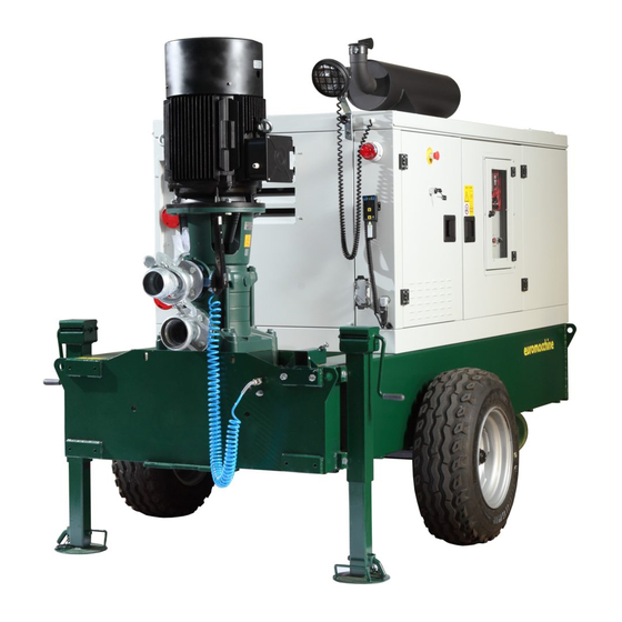
IDENTIFICATION OF THE MACHINE GENERAL DESCRIPTION The LAMPO Multifunction Unit can be used simultaneously as generator set and as motor pump with the possibility of changing the flow rates and pressures through inverter. The machine consists of an internal combustion diesel engine, coupled with a self-regulating alternator to produce the electricity required for the operation of the submersible centrifugal type electric pump with one or more impellers. -
Page 13: Data And Ce Marking
The clothing of those who work or maintain the machine must comply with the essential safety requirements defined by the Community Directives 89/656/EEC and 89/686/EEC and the laws in force in the country. In order to avoid risks of dragging, entrapment and other, it is recommended not to wear bracelets, watches, rings, necklaces or fluttering clothing DATA AND CE MARKING According to Directive 2006/42/EC the machine must be marked, before com- missioning, with the CE marking through which the manufacturer declares,... -
Page 14: Machine Layout
MACHINE LAYOUT 1.5.1 SINGLE PUMP VERSION 1.5.2 VERSION WITHOUT PUMP 1.5.3 DOUBLE PUMP VERSION 1.5.4 VERTICAL / HORIZONTAL PUMP VERSION POSITION DESCRIPTION POSITION DESCRIPTION Soundproofed generator set Exhaust Engine control unit Service socket panel Control panel Indicator light Inverter compartment Electric pump up/down command Emergency button Vertical electric pump... -
Page 15: True Copy Of The Original Of Ec Declaration Of Conformity
E - Persona lícita a la redacción de die technischen Unterlagen het bewerken van het technisch la documentación técnica zusammenzustellen: dossier: EUROMACCHINE S.r.l. - Via delle industrie, 20 - 31047 Ponte di Piave TV Descrizione Beschreibung Description Beschrijving Description Descripción... -
Page 16: Transport, Storage And Installation
TRANSPORT, STORAGE AND INSTALLATION QUALIFIED OPERATORS INVOLVED IN SECTION REQUIRED PPE - RESIDUAL RISKS HANDLING THE PACKED MACHINE Case unloading, transport and handling Upon arrival, the parts of the machine must be unloaded and handled with the maximum care, carefully following the instructions given on the walls of the cases or those contained in this manual. -
Page 17: Handling The Machine
HANDLING THE MACHINE Unloading, transport and handling Upon arrival, the parts of the machine, protected only by weather cover, must be handled with the maximum care, carefully following any indications given on them or those contained in this Instruction Manual. If during lifting the slings come into contact with parts of the machine, it is necessary to intervene, interposing protective materials between the parts, to avoid damage to the machine and the wearing of the sling (highly dangerous). -
Page 18: Levelling
The system of "mobile" or "removable" towing eyes consists of a support integral to the helm, to which, in addition to the two types of "fixed" eyes, a further model can be applied through a coupling plate. With the mobile towing eye system it is possible to limit the displacement of the Lampo Green machine. “GERMANY” TYPE - DIN 74054 “ITALY”... -
Page 19: Submersible Electric Pump
For no reason the machine can be used with stabilisers not resting on the ground. For no reason the machine can be used on sloping terrain. CORRECT INSTALLATION INCORRECT INSTALLATION Make sure that the machine is always in a horizontal position, both during operation and during transport. If the machine is tilted, fuel leaks may occur. Do not lift the machine excessively with the stabilisers. -
Page 20: Commissioning
COMMISSIONING QUALIFIED OPERATORS INVOLVED IN SECTION REQUIRED PPE - RESIDUAL RISKS PRELIMINARY TESTS Before machine commissioning, it is necessary to carry out a series of checks in order to prevent errors or accidents during its use: • Check that the machine has not been damaged during assembly/transport phase •... -
Page 21: Supply
The use of a bactericidal additive helps prevent the formation of bacteria, fungi and moulds, stabilises the diesel and prevents its oxidation. Euromacchine recommends the constant use of a bactericidal additive in the machine and in the Diesel stocking tanks to prevent malfunctions and/or breakages. -
Page 22: Ground Connection
GROUND CONNECTION >1.5 mt Fasten the ground plate as shown in the figure. Signal the presence of the ground plate with proper signs. With ground resistivity equal to 50 Ohm, the plate must be fixed at a depth of 1.5 metres, thus ensuring the maximum safety. For no reason the machine can be used without plate installed in the ground. -
Page 23: Operation
OPERATION QUALIFIED OPERATORS INVOLVED IN SECTION RESIDUAL RISKS FOR THE OPERATOR IN CHARGE OF THE OPERATION Although many accident prevention devices have been used on the machine in order to eliminate the possible risks of use for the operator, it has some areas defined “RESIDUAL RISK AREAS”. -
Page 24: Emissions
EMISSIONS During normal operation, the machine does not emit significant noise emissions (< 80dB), therefore the personal protective equipment for hearing protection ARE NOT MANDATORY. Exception is made for use with open doors during maintenance or setup of the machine, where the machine emits significant sound emissions (> 80 dB), therefore the personal protective equipment IS MANDATORY. - Page 25 4.7.2 ENGINE CONTROL UNIT 4.7.2.1 CEM 120 VERSION DESCRIPTION TYPE DESCRIPTION TYPE Processing time setting Button Operation selector Button Electronic pressure switch adjustment Button Show instruments / Alarm silencing Button Disabled pump protection indicator Warning light Control unit running Warning light Pump protection disabling / enabling Button Active pump protection...
- Page 26 4.7.2.2 CIM 136 VERSION DESCRIPTION TYPE DESCRIPTION TYPE Programming Button Call present Warning light Pump protection disabling / enabling Button pump priming (missing if flashing) Warning light SMS receiving /sending activity Warning light Can/bus parameters Warning light System error - No SIM card Warning light Field signal Warning light...
- Page 27 4.7.3 ELECTRIC PUMP PUSH-BUTTON PANEL DESCRIPTION Downstroke Occupied hands command Upstroke Operation light 4.7.4 SERVICE SOCKET PANEL DESCRIPTION Circuit breaker Service socket - Three-phase 32A Submersible pump disabling / enabling (*) Three-phase 63A service socket (optional) Pump socket Submersible pump start / stop (*) Submersible pump start / stop (*) Secondary flag socket (*) E-Vacuum Start / Stop / E-Self pump start...
-
Page 28: Start-Up
START-UP With machine stationary and stable, placed near the water basin, with stabilising feet on the ground and installed ground connection, follow the instructions below: Before engine start-up, check that the service sockets are free and the circuit breakers are lowered to prevent sudden starts. Never cover the machine during its operation. - Page 29 Euromacchine s.r.l. accepts no liability for well inadequacy or for any falls. Always check the correct connection of the blue spiral wound hose to the machine pressure switch.
- Page 30 DESCRIPTION CIM-136 CEM-120 DESCRIPTION CIM-136 CEM-120 13. Remove the electric pump plug from the 14. Before starting the pump, check that the cable winder and connect it to the socket potentiometer is at minimum. on the panel. (for version with CEM 120 only). START 15.
- Page 31 4.8.3.1 E-PLUTO PUMP PRIMING POSITION DESCRIPTION Pluto lever Pluto connection valve Delivery valve Pluto exhaust DESCRIPTION CIM-136 CEM-120 DESCRIPTION CIM-136 CEM-120 Make sure of machine stability and its CONTROL UNIT ground connection, turn the control Press “Function” key to select the manual unit on using the “Control Unit OFF-ON”...
- Page 32 DESCRIPTION CIM-136 CEM-120 DESCRIPTION CIM-136 CEM-120 START Start the pump using the key: • CIM 136: “HARE” key on the control unit • CEM 120: “START” key on the control panel 12. Gradually open the pump delivery valve (3) It is recommended to start the pump with potentiometer at minimum.
- Page 33 DESCRIPTION CIM-136 CEM-120 DESCRIPTION CIM-136 CEM-120 Enable the auxiliary circuits from the LAMPO command and control unit (Fig. 5.12) (for version with CEM 120 only). Close the pump delivery valve (3) Open E-Vacuum vacuum system cock (5) 10. Before starting the pump, check that the potentiometer is at minimum.
- Page 34 4.8.3.3 PUMP PRIMING - E-SELF POSITION DESCRIPTION Delivery valve Filling cock E-Self E-Self Suction Start / Stop Vent DESCRIPTION CIM-136 CEM-120 DESCRIPTION CIM-136 CEM-120 Make sure of machine stability and its Press “Function” key to select the manual ground connection, turn the control operation mode unit on using the “Control Unit OFF-ON”...
- Page 35 DESCRIPTION CIM-136 CEM-120 DESCRIPTION CIM-136 CEM-120 15. Start the pump using the key: 16. Gradually open the delivery valve (1) • START CIM 136: “HARE” key on the control unit • CEM 120: “START” key on the control panel It is recommended to start the pump with potentiometer at minimum.
- Page 36 4.8.4 LAMPO VERSION - DOUBLE PUMP SUB+VP Before starting the operations described in the points below, make sure that the electric pump is enabled by positioning the switch on the service socket panel on “SUB+VP” (see 6.8.5 control position 6). DESCRIPTION CIM-136 CEM-120...
-
Page 37: Service Utilities
DESCRIPTION CIM-136 CEM-120 DESCRIPTION CIM-136 CEM-120 13. Start the submersible electric pump by position the selector present on the Service socket panel to START (see 4.7.4 14. Before starting the pump, check that the selector position 6) STOP START potentiometer is at minimum. (for version with CEM 120 only). -
Page 38: 4.10 Machine Stop
4.10 MACHINE STOP Before switching the machine off, check that the service sockets are free and the circuit breakers are lowered to prevent sudden starts upon the following machine start-up. DESCRIPTION CIM-136 CEM-120 DESCRIPTION CIM-136 CEM-120 Press “Pump protection disabling/ enabling”... -
Page 39: Maintenance And Cleaning
MAINTENANCE AND CLEANING QUALIFIED OPERATORS INVOLVED IN SECTION Maintenance operations, such as inspection, adjustment or repair, must be carried out by qualified personnel only. REQUIRED PPE - RESIDUAL RISKS SAFETY PRECAUTIONS Before carrying out any type of Maintenance or Repair, it is necessary to insulate the machine from power supply. During Maintenance or Repair works it is advisable to apply the following recommendations: •... - Page 40 Nature and frequency of periodic maintenance operations. To ensure the correct operation of the machine, it is useful and appropriate to schedule a general maintenance at least once a year. This operation has the purpose of preventing extraordinary maintenance operations with consequent machine downtime during the period of use. All mechanical, electrical, pneumatic and hydraulic components must be checked.
- Page 41 5.5.2 ENGINE SECTION Check Replace Contact the supplier Replace - Operations for new machine and after a long machine downtime. Every Every Every Part Checks After 20 Every 50 Every 250 1000 2000 hours hours hours hours hours hours Check and fill with engine coolant Check and clean radiator tabs Cooling Check and adjust the cooling fan belt...
- Page 42 CAUSES AND REMEDIES In case of malfunction or failure, the machine signals several alarms to the operator via control panel. Below is the complete list CONTROL UNIT INCONVENIENCE POSSIBLE CAUSES SOLUTIONS Low battery Charge/change the battery Battery isolator set to “OFF” Set to “ON”...
- Page 43 INVERTER INCONVENIENCE POSSIBLE CAUSES SOLUTIONS Check the item “The alternator does not supply The generator set does not supply power power” for possible causes The inverter does not turn on Main switch Q1 not enabled Restore the main switch Q1 closure Inverter faulty Contact the technical service “AUX”...
- Page 44 MOST COMMON INVERTER ALARMS INCONVENIENCE POSSIBLE CAUSES SOLUTIONS Reset the inverter A045 (Bypass Fault) Breakage of relay or pre-charge contactor If the contactor is broken, replace it inside the inverter Reset the inverter A046 (Bypass Connector Fault) Breakage of relay or pre-charge contactor If the contactor is broken, replace it inside the inverter Check the item “The alternator does not supply...
- Page 45 ELECTRIC PUMP INCONVENIENCE POSSIBLE CAUSES SOLUTIONS Motor/pump coupling in wrong position Restore the correct coupling position and lock it Motor/pump coupling broken Replace the coupling Pump shaft broken Restore the pump The electric pump does not turn The electric pump is blocked due to the presence Remove the foreign bodies/rust from the pump of foreign bodies/rust body...
- Page 46 PRIMING SYSTEMS INCONVENIENCE POSSIBLE CAUSES SOLUTIONS No water inside the E-Self electric pump Add water to the E-Self electric pump Pipe inverted Connect the pipes correctly The E-Self electric pump does not prime Air infiltrations during E-Self electric pump Check the suction pipe of the E-Self electric pump; suction Delivery gate valve open Close the electric pump delivery gate valve...
- Page 47 MAINTENANCE LOGBOOK BY THE DISTRIBUTOR’S CUSTOMER An accurate compilation of the maintenance and repair logbook allows the personnel in charge to monitor the operations performed on the system, making subsequent interventions more effective. The evidence of (preventive, corrective, ordinary and extraordinary) maintenance operations must be kept and made available for control bodies for a minimum of 3 years.
- Page 48 MACHINE INACTIVITY Short period of machine inactivity. Short period of machine inactivity. “Short” means a period not exceeding 15 days. . During this period it is necessary to continue the normal preventive and ordinary maintenance provided for in the specific Section 5 Maintenance. Long period of machine inactivity “Long”...
- Page 49 LIST OF SPARE PARTS QUALIFIED OPERATORS INVOLVED IN SECTION For any spare part, contact the Manufacturer. ALWAYS USE ORIGINAL SPARE PARTS. The manufacturer is not responsible for breakages, malfunctions or damage to persons or property resulting from the use of non-original parts. For spare parts management, the Manufacturer provides the module below that allows a quick identification of the part to be requested.
- Page 50 MACHINE DECOMMISSIONING QUALIFIED OPERATORS INVOLVED IN SECTION INFORMATION FOR DECOMMISSIONING At the end of the machine lifecycle, provide for its demolition and disposal by relying on specialised and authorised companies, according to the regulations in force. The dismantling operations must be entrusted to qualified personnel and be carried out in a safe manner. The machine is made of non-biodegradable materials.
- Page 51 LAMPO Multifunction Unit...
- Page 52 LAMPO Multifunction Unit...
- Page 53 LAMPO Multifunction Unit...
- Page 54 LAMPO Multifunction Unit...
- Page 55 LAMPO Multifunction Unit...
- Page 56 LAMPO Multifunction Unit...
- Page 57 LAMPO Multifunction Unit...
- Page 58 LAMPO Multifunction Unit...
- Page 59 LAMPO Multifunction Unit...
- Page 60 LAMPO Multifunction Unit...
- Page 61 LAMPO Multifunction Unit...
- Page 62 LAMPO Multifunction Unit...
- Page 63 LAMPO Multifunction Unit...
- Page 64 LAMPO Multifunction Unit...
- Page 65 LAMPO Multifunction Unit...
- Page 66 LAMPO Multifunction Unit...
- Page 67 LAMPO Multifunction Unit...
- Page 68 LAMPO Multifunction Unit...
- Page 69 LAMPO Multifunction Unit...
- Page 70 LAMPO Multifunction Unit...
- Page 71 LAMPO Multifunction Unit...
- Page 72 LAMPO Multifunction Unit...
- Page 73 LAMPO Multifunction Unit...
- Page 74 LAMPO Multifunction Unit...
- Page 75 LAMPO Multifunction Unit...
- Page 76 LAMPO Multifunction Unit...
- Page 77 LAMPO Multifunction Unit...
- Page 78 LAMPO Multifunction Unit...
- Page 79 LAMPO Multifunction Unit...
- Page 80 LAMPO Multifunction Unit...
- Page 81 LAMPO Multifunction Unit...
- Page 82 LAMPO Multifunction Unit...
- Page 83 LAMPO Multifunction Unit...
- Page 84 Euromacchine S.r.l. Via delle Industrie, 20 (+39) 0422 853200/01 31047 – Ponte di Piave (TV) info@euromacchine.it www.euromacchine.com 2019 Italy...
Need help?
Do you have a question about the LAMPO GREEN and is the answer not in the manual?
Questions and answers
какой объем бака
The tank capacity of the Euromacchine GREEN is 450, 650, or 1,000 liters.
This answer is automatically generated