Table of Contents
Advertisement
Quick Links
Advertisement
Table of Contents

Related Manuals for Deimic ONE Master

Summary of Contents for Deimic ONE Master
- Page 1 ONE Master Installation guide smart home for everyone...
-
Page 2: Table Of Contents
CONTENS WARNINGS ............................1 1. DEiMiC ONE MASTER DEVICE SPECIFICATION ................. 3 1.1. DESCRIPTION..........................3 1.2. TECHNICAL DATA ........................4 1.3. THE DEVICE PINOUT DESCRIPTION ................... 5 1.4. APPLICATIONS .......................... 6 2. ASSEMBLY ........................... 7 2.1. PREPARATION TO ASSEMBLY ....................7 2.2. -
Page 3: Warnings
DEiMiC company products are not intended for use in medicine, avionics and industry. DEiMiC company devices should be installed inside rooms, in places available for a fitter and conservator. Remember to ensure proper ventilation for the device and do not expose it to the effects of weather conditions. - Page 4 Installation guide DEiMiC ONE MASTER v1.8 WARNINGS (continued) Utilization of waste electrical and electronic equipment is regulated by the EU directive 2002/96/EC. The Directive prohibits disposal of waste electrical and electronic equipment with other garbage under penalty of a fine.
-
Page 5: Deimic One Master Device Specification
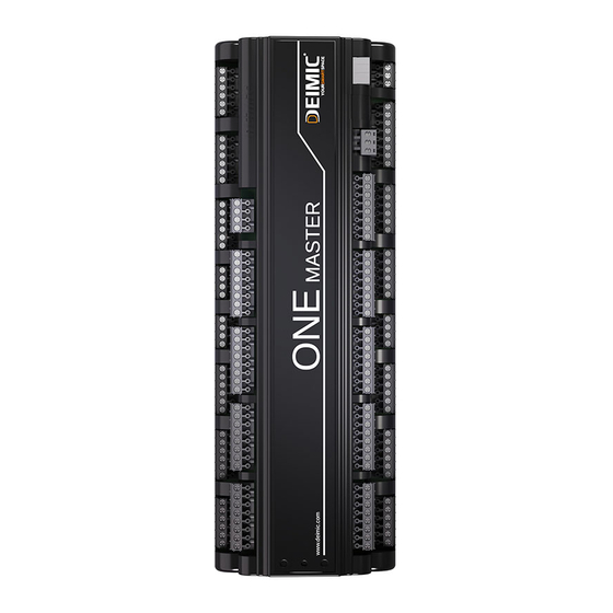
1.1. DESCRIPTION Figure 1. DEiMiC ONE MASTER device DEiMiC ONE MASTER device is a base of intelligent building control system. The device contains 55 inputs (e.g. for switches connections), 36 relay outputs, 4 outputs dedicated to gates control and 4 dimmable LED outputs. Six of the inputs are dedicated to motion sensors connections. -
Page 6: Technical Data
Installation guide DEiMiC ONE MASTER v1.8 1.2. TECHNICAL DATA Tab. 1. DEiMiC ONE MASTER device parameters Parameter Value Number of high-current relay outputs Number of low-current relay outputs (1 A, 250 V AC) Number of dimmable LED outputs (12 V or 24 V) -
Page 7: The Device Pinout Description
Installation guide DEiMiC ONE MASTER v1.8 1.3. THE DEVICE PINOUT DESCRIPTION... -
Page 8: Applications
Installation guide DEiMiC ONE MASTER v1.8 1.4. APPLICATIONS DEiMiC smart home system provides control of all electrical devices inside a building such as lights, shutters, car gates and garage gates, heating devices, alarms, irrigation devices, ventilation and sound systems. The device is cooperating with motion sensors, temperature sensors and switches. -
Page 9: Assembly
Installation guide DEiMiC ONE MASTER v1.8 2. ASSEMBLY EVERY INSTALLATION WORK SHOLUD BE DONE WITH POWER OFF BEFORE ASSEMBLY, IT IS NECESSARY TO READ THE INSTRUCTION, ESPECIALLY THE WARNINGS ON PAGE 1 2.1. PREPARATION TO ASSEMBLY During assembly the following tools may be useful:... -
Page 10: Guidelines
Installation guide DEiMiC ONE MASTER v1.8 2.2. GUIDELINES 2.2.1. WIRES During wires installation it is recommended to ensure appropriate space between low-voltage wires and mains electricity wires. It is recommended to avoid situations where signals wires are placed parallel to the mains electricity wires. - Page 11 Installation guide DEiMiC ONE MASTER v1.8 You should use good quality cables only. Choose UTP cat. 5 cables which are made from copper. 6. A 1 mm multi-conductor cable should be lead to heating distributors (number of the cable conductors = quantity of valves + 2).
-
Page 12: Electrical Switchgear
The control cabinet should be protected against unauthorized access. 1. Dimensions of an electrical switchgear should be adjusted to quantity of installation modules and protections. One DEiMiC module uses space of 18 modules. 2. Electrical equipment, protective and residual-current devices should be chosen and installed by a electrician only. -
Page 13: Connections Inside Electrical Switchgear
DEiMiC ONE MASTER v1.8 2.2.3. CONNECTIONS INSIDE ELECTRICAL SWITCHGEAR 1. Every building outgoing wire, which are not controlled by the DEiMiC system (electric sockets, furnace, alarm, fridge power supplies etc.) should be connected to circuits breakers like in traditional installations. -
Page 14: Marking
Installation guide DEiMiC ONE MASTER v1.8 2.2.3. CONNECTIONS INSIDE ELECTRICAL SWITCHGEAR (continued) i) Heating distributors outgoing wires should be connected with valves, inside hermetic boxes, led out with terminal form an electrical switchgear side and described according to documentation delivered by central heating installer (room names assigned to the valves). -
Page 15: Good Advices
Installation guide DEiMiC ONE MASTER v1.8 2.2.5. GOOD ADVICES 1. Dimensions of an electrical switchgear should be properly chosen due to possibility of a need more number of devices than expected (more space also makes installation work more comfortable). 2. A twisted-pair cable and a coaxial cable should be routed from an electrical box to a control cabinet (it will make easier future phone/network/TV connection). - Page 16 Installation guide DEiMiC ONE MASTER v1.8 2.2.5. GOOD ADVICES (continued) 7. Check shutters and other drives connections in terms of properly work and terminals direction sequence. 8. Temporary installation, used by workers, should be connected to the switchgear after finishing a connection.
-
Page 17: Examples Of Wiring Diagrams
Installation guide DEiMiC ONE MASTER v1.8 3. EXAMPLES OF WIRING DIAGRAMS 3.1. POWER SUPPLY CONNECTION Figure 4. Power supply connection diagram... -
Page 18: Network Connection
Installation guide DEiMiC ONE MASTER v1.8 3.2. NETWORK CONNECTION Default IP: 192.168.1.99 Figure 5. Network connection diagram... -
Page 19: Outputs Connection - Lights
Installation guide DEiMiC ONE MASTER v1.8 3.3. OUTPUTS CONNECTION - LIGHTS Figure 6. Lights connection diagram... -
Page 20: Outputs Connection - Shutters
Installation guide DEiMiC ONE MASTER v1.8 3.4. OUTPUTS CONNECTION – SHUTTERS Figure 7. Shutters connection diagram... -
Page 21: Outputs Connections - Gates, Gateways
Installation guide DEiMiC ONE MASTER v1.8 3.5. OUTPUTS CONNECTIONS – GATES, GATEWAYS Figure 8. Gates and gateways connection diagram... -
Page 22: Outpus Connections - Led Lights
Installation guide DEiMiC ONE MASTER v1.8 3.6. OUTPUS CONNECTIONS – LED LIGHTS OPTION 1 - THE DEVICE SWITCHES LEDS POWER SUPPLIER Figure 9. LEDs connection diagram – option 1... - Page 23 Installation guide DEiMiC ONE MASTER v1.8 OPTION 2 - LEDS POWER SUPPLIERS EXTERNALLY CONECTED TO MAINS ELECTRICITY Figure 10. LEDs connection diagram – option 2...
-
Page 24: Outputs Connection - Contactors
Installation guide DEiMiC ONE MASTER v1.8 3.7. OUTPUTS CONNECTION – CONTACTORS Figure 11. Contactors connection diagram... -
Page 25: Inputs Connetion - Switches And Buttons
Installation guide DEiMiC ONE MASTER v1.8 3.8. INPUTS CONNETION – SWITCHES AND BUTTONS Figure 12. Inputs connection diagram... -
Page 26: Motion Sensors Connection
Installation guide DEiMiC ONE MASTER v1.8 3.9. MOTION SENSORS CONNECTION Figure 13. Motion sensors connection diagram... -
Page 27: Extensions Modules Connection
Installation guide DEiMiC ONE MASTER v1.8 3.10. EXTENSIONS MODULES CONNECTION Incorrect connection (!) it may damage the devices. Straight Cable must be used rather than Crossover Cable. Figure 14. Extension modules connection diagram... -
Page 28: First Start
DEiMiC ONE MASTER v1.8 4. FIRST START 4.1. TEST BUTTON DEiMiC ONE MASTER has been equipment with a test button. All odd numbered outputs will be turned on after the button pressed. 2 press of the button deactivates odd numbered outputs and activates even numbered outputs. -
Page 29: First Start Of Deimic One Application
DEiMiC ONE MASTER v1.8 4.3. FIRST START OF DEiMiC ONE APPLICATION During first application start, enter the server address and the code, placed on the DEiMiC ONE device. For further information and detailed DEiMiC system configuration tutorial please visit our channel: https://vimeo.com/deimic... -
Page 30: Guidelines
Following text includes information about requirements which have to be met to ensure the system control capability of roller blinds and shutters. Drives are controlled by the DEiMiC system via relay system which can be open, closed or impulse controlled, depending on a needs and specification of the given drive. - Page 31 Installation guide DEiMiC ONE MASTER v1.8 5.1. ROLLER BLINDS, SHUTTERS AND MARQUISE (continued) 4. If you are planning to connect the drives with additional sensors (e.g. wind sensor, dusk sensor), it is necessary to inform the system installer about this fact. In marquise case, they have to be equipped with an independent wind sensor, which will automatically close the marquise in case of a strong wind, which may damage it.
-
Page 32: Gate Drives
Following text includes information about requirements which have to be met to ensure the system control capability of car gates. Drives are controlled by the DEiMiC system via relay system which can be open, closed or impulse controlled depending on a needs and specification of the given drive. -
Page 33: Central Heating
Following text includes information about requirements which have to be met to ensure the system control capability of heating and DHW circulation pump. Heating are controlled by the DEiMiC system via closing heat supply valves. The temperature sensors should be installed in the chosen rooms. - Page 34 DEiMiC ONE MASTER v1.8 5.3. CENTRAL HEATING (continued) 4. If DHW circulation pump should be controlled by DEiMiC system, the pump must have auto start function (after power on pump should start working). An electrician should be informed about a need to route 3x1,5mm wire to a DHW circulation pump (hot, neutral and ground wire).
-
Page 35: Revision History
Version Changes 05.2014 initial release added wiring diagrams changed the device (more number inputs/outputs, added 05.06.2014 functional capabilities) added new wiring diagrams and information about DEiMiC ONE COMFORT changed information about extension modules added industry guidelines added test button description... - Page 36 Installation guide DEiMiC ONE MASTER v1.8 Installer notes ............................................................................................................................................................................................................................................................................................................................................................................................................................................................................................................................................................................................................................................
- Page 37 Installation guide DEiMiC ONE MASTER v1.8 Installer notes ............................................................................................................................................................................................................................................................................................................................................................................................................................................................................................................................................................................................................................................
- Page 38 TERMS OF THE WARRANTY CODE 1. DEiMiC SP. z o. o. grants five years of warranty, which starts from the date of the product acquisition by the final user, for produced by the DEiMiC SP. z o. o. company product, pointed on identification sticker placed on the warranty card.
- Page 39 PRODUCT REMARKS: ..................................................................................................................................................................................................................................... (fills the seller or the installer in case of purchasing the device after price reduction) ……………………………. ……………………………. Signature Stamp of the producer or seller Repair date Repair description...
- Page 40 © 2015 DEiMiC...
Need help?
Do you have a question about the ONE Master and is the answer not in the manual?
Questions and answers