Table of Contents
Advertisement
Quick Links
Advertisement
Table of Contents

Related Manuals for IBA ibaLink-SM-64-io

Summary of Contents for IBA ibaLink-SM-64-io
- Page 1 System Interface for SIMATIC S5 and MMC Manual Issue 3.6...
- Page 2 Required corrections are contained in the following regulations or can be down- loaded on the Internet. The current version is available for download on our web site http://www.iba-ag.com. Windows® is a label and registered trademark of the Microsoft Corporation. Other prod- uct and company names mentioned in this manual can be labels or registered trade- marks of the corresponding owners.
-
Page 3: Table Of Contents
Manual Table of contents About this manual ................... 5 Target group ....................5 Notations ....................... 5 Used symbols....................6 Introduction ..................... 7 Scope of delivery..................... 8 System requirements ..................9 Hardware ...................... 9 Software ......................9 Installation / Deinstallation ................10 Installing the Card .................. - Page 4 Manual ibaLink-SM-64-io 8.3.1 Data blocks and Offset Assignment ............. 27 Switch Layout and Application Examples ............ 29 Multi-Processor Mode 155U ................ 30 The simultaneous (bidirectional) send and receive mode (135U) ....33 Special features of S5-150U ............... 35 Technical Data ....................36 Support and contact ..................
-
Page 5: About This Manual
Manual About this manual This manual describes the construction, the use and the operation of the device ibaLink- SM-64-io. Target group This manual addresses in particular the qualified professionals who are familiar with han- dling electrical and electronic modules as well as communication and measurement tech- nology. -
Page 6: Used Symbols
Manual ibaLink-SM-64-io Used symbols If safety instructions or other notes are used in this manual, they mean: The non-observance of this safety information may result in an imminent risk of death or severe injury: By an electric shock! Due to the improper handling of software products which are coupled to... -
Page 7: Introduction
S5 or MMC system. The data to be measured are written into this memory range by the system where the card is plugged in and are transmitted over an iba standard fiber optical interface with 3.3 Mbit/s to the iba system. -
Page 8: Scope Of Delivery
Manual ibaLink-SM-64-io Scope of delivery ibaLink-SM-64-io board ibaLink-SM-64-io manual S5- function blocks (on DVD “iba Software & Manuals”) P23-k1st.s5d for S5-115U (941-944) Cache Mode P23-k2st.s5d for S5-115U (945) Cache Mode P23-k3st.s5d for S5-135U (928) Cache Mode ... -
Page 9: System Requirements
For measuring on a notebook computer an ibaCom-PCMCIA-F card (type 2) and the corresponding spiral cable are required. In order to realize a frame-to-frame connection a second ibaLink-SM-64-io card or an- other iba component such as ibaLink-MBII-2io or ibaLink-SM-128V-i-2o (VMEbus) is re- quired. -
Page 10: Installation / Deinstallation
Installation / Deinstallation Each ibaLink-SM-64-io board occupies a single slot in the S5 and/or MMC rack. The EGB standards for handling electrostatic sensitive devices must be followed. Use a ground line or discharge any electrostatic charge from yourself before touching the card. -
Page 11: Product Characteristics
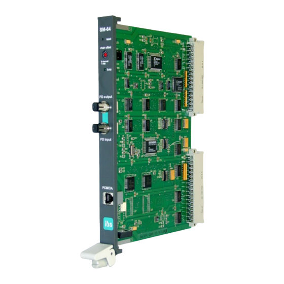
Manual Product Characteristics Connectors and Operational Elements on Front Panel Reset-button Coding Switch (chain offset) Status LED (busy) Sender (FO output) Receiver (FO input) RJ11 Notebook computer connector Lower grip and screw Figure 1: Front panel Issue 3.6... -
Page 12: Reset Button
Depressing this switch resets the board. When the button is depressed the board can not be accessed by the system. Please note, that in certain instances, this may cause disturbances within a host system, when the ibaLink-SM-64-io card refuses bus access requests during reset. -
Page 13: Led Status
The switch setting 9 of the rotary switch at the front panel activates the additional receiver mode of the ibaLink-SM-64-io. In this transmission mode it is possible to receive and send 64 analog plus 64 binary signals in both directions. No cascading is possible in this mode of operation If the rotary switch is turned during operation, incorrect telegrams are generated. -
Page 14: Connectors And Switches On Board
Manual ibaLink-SM-64-io Connectors and Switches on Board On the assembly side of the board there are three DIL-switches which are used to set the format of the data to be transmitted and received on the fiber optical channels. Position of the elements... -
Page 15: S5 Applications: Switch Settings On The Board
Manual 6.2.1 S5 Applications: Switch Settings on the Board The sequence of the switches corresponds to the layout on the board. Addressing: S5-Linear Mode: S5-Cache Mode: Address Settings 8-bit Cache Number Settings OFF (=0) ON (=1) OFF (=0) ON (=1) -
Page 16: Mmc Applications: Switch Settings On The Board
Manual ibaLink-SM-64-io 6.2.2 MMC Applications: Switch Settings on the Board The sequence of the switches corresponds to the layout on the board Addressing Section 2: OFF (=0) ON (=1) Addr. 11 = 0 Addr. 11 = 1 Addr. 12 = 0 Addr. -
Page 17: Backplane Connector
Manual Setup Example: CE800 Switch settings: ---SW3--- ---SW1--- ---SW4--- 1011 1000 1011 0110 1100 0000 Address 19 18 17 16 15 14 13 12 11 10 09 08 07 06 05 04 03 02 01 00 X=on/0=off X X 0 0... -
Page 18: Cascading Boards (Loop Mode)
Values from unused Cascade Input It is possible to change the fiber optic connec- tion during operation. Compatibility 32-Bit-Mode: The 32-bit mode of the new S5/MMC interface board (ibaLink-SM-64-io) now transmits 4 telegrams in the sequence EE, EB, E8 and E5. Issue 3.6... -
Page 19: Memory Organization
Manual Memory Organization The board supports three memory access modes: S5 Bus Linear mode S5 Bus Cache mode MMC Linear - Bus mode. The board contains 2KB of dual-port RAM interfaced to 16-bit data bus. The bus can be set to operate in 8-bit mode when the cache or linear access mode is used. -
Page 20: Transmit Telegrams Via The Fiber Optic Connections
Status of the Acquisition Units Bit0 = 1: Test Operation (Real -Transfer) Bit1 = 1: Reception of S5-Reals Bit2 = 1: Reception Error from ibaLink-SM-64-io Bit3 = 1: Operating in Real-Mode (0 = Integer) Byte 67: Rotary Switch Setting of the ibaLink-SM-64-io... -
Page 21: System Topologies And Application
Manual System Topologies and Application Multiple system topologies are possible with the ibaLink-SM-64-io without the request for special settings. The operating mode of the ibaLink-SM-64-io is a consequence of the desired topology. Peer-to-Peer Operation (frame-to-frame connection) If the device shall run in loopback mode (output coupled to own input) or two ibaLink- SM-64-io cards shall run directly coupled the mode switch of both cards must be set to position 9. -
Page 22: Ibapda Application
Manual ibaLink-SM-64-io ibaPDA Application In classic combination of ibaLink-SM-64-io and ibaPDA the fiber optic output link is con- nected to an input link on an ibaFOB-io, ibaFOB-4i-S, ibaFOB-2io-X or ibaFOB-4i-X card. The link transmits 64 analog and 64 digital signals. -
Page 23: Ibalogic Application
In order to use the outputs of the ibaLogic application the fiber optic input link (FO input) of the ibaLink-SM-64-io card must be connected to the output link of an ibaFOB-io- or ibaFOB-4o card in the ibaLogic-PC. This link as well receives 64 analog and 64 digital signals. -
Page 24: I/O Mode Of Operation
The ibaLink-SM-64-io can serve as a process i/o bus extender for PLC systems. In order to transmit output data from the S5 or MMC system via the ibaLink-SM-64-io card the ibaPADU-8-O device can be used. For the input direction ibaPADU-8 devices may be used. -
Page 25: S5 - Function Blocks And Modes Of Operation
Manual S5 – Function Blocks and Modes of operation S5 - Function Blocks The function blocks are stored in the following files: P23-k1st.s5d for S5-115U (941-944) cache mode P23-k2st.s5d for S5-115U (945) cache mode P23-k3st.s5d for S5-135U (928) cache mode P23-k4st.s5d... -
Page 26: Function Blocks
Manual ibaLink-SM-64-io Function Blocks FB30 - Real - Default FB31 - Real - Cyclic Data Transfer FB32 - Integer - Default FB33 - Integer - Cyclic Data Transfer All FBs utilize one data block. This data block contains saved analog and digital data (as described above) as well as internal auxiliary data for the function block. -
Page 27: Data Blocks And Offset Assignment
Manual 8.3.1 Data blocks and Offset Assignment 8.3.1.1 Data Block for Real Transfers Figure 8: Data blocks for real transfers Issue 3.6... - Page 28 Manual ibaLink-SM-64-io 8.3.1.2 Data Block for Integer Transfers Figure 9: Data blocks for integer transfers Issue 3.6...
-
Page 29: Switch Layout And Application Examples
Manual Switch Layout and Application Examples The files contain run time S5 programs. The following switch setup is required on the board. For 135U/155U (real) Miscellaneous 1 - OFF 1 - OFF 1 - ON This switch setup defines the following... -
Page 30: Multi-Processor Mode 155U
Manual ibaLink-SM-64-io Multi-Processor Mode 155U (File: P23-m5st.s5d) The file P23-m5st.s5d contains two function blocks that have been conceived for multi- processor applications. The measurement values can be inserted into subranges. The FB invoke command defines which measurement channels are concerned. The total... - Page 31 Manual FX250: Entering Real Values This function block transfers a closed set of real values to the ibaLink-SM64-io interface board. The set must lie within an existing DB or DX in the range DW0-DW255. Parameters: DBDX D/KY - Data block NR DL=0 then DB / DL><0 then DX, DR=DB/DX-No.
- Page 32 Manual ibaLink-SM-64-io Examples: BA FX250 Real values in KG format DBDX 0,40 The data is contained in DB40 Start of block DW120 ANLG 10,8 8 channels are transmitted; channel 10 - channel 17 A000 One block from address FA000H is utilized...
-
Page 33: The Simultaneous (Bidirectional) Send And Receive Mode (135U)
The simultaneous (bidirectional) send and receive mode (135U) (file P23-k3st.s5d) This special mode enables the additional send capability of the ibaLink-SM-64-io for the This mode is selected when the rotary switch is set to position 9. This mode is available only in S5 cache mode ... - Page 34 Manual ibaLink-SM-64-io QUIT Codes OK, computing with data transfer OK, computing without data transfer Data flow was interrupted Handshake error Transmission disturbed, not receiving Startup failure Card could not be recognized ibaSM64 firmware and FBs have different versions Cache access error...
-
Page 35: Special Features Of S5-150U
Manual Special features of S5-150U In addition to the information given in chapter 8, the following must be observed for the S5-150U. The program package for the S5-150U(S) family can be found in file P23-K4st.s5d. Four FBs are mainly available here: ... -
Page 36: Technical Data
Galvanic isolation by fiber optic FO connectors ST Lean 62.5 / 125 μm Compatibility The ibaLink-SM-64-io interface has been tested with the following S5 racks and CPUs: S5-155U, CPU 948 S5-150U, CPU 924-927 S5-135U, CPS5U 928B S5-115U, CPU 941B, 942B, 943B, 944B... -
Page 37: Support And Contact
Mailing address iba AG Postbox 1828 D-90708 Fuerth Germany Delivery address iba AG Gebhardtstrasse 10 D-90762 Fuerth Germany Regional and Worldwide For contact data of your regional iba office or representative please refer to our web site www.iba-ag.com. Issue 3.6...
Need help?
Do you have a question about the ibaLink-SM-64-io and is the answer not in the manual?
Questions and answers