
Subscribe to Our Youtube Channel
Summary of Contents for Fronius FDV 22 MF
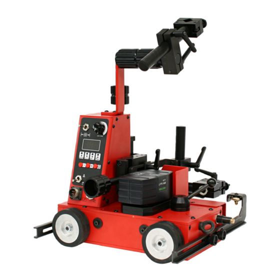
- Page 1 / Perfect Welding / Solar Energy / Perfect Charging Operating Instructions FDV 22 MF Carriage 42,0410,1645 V09 - 03082016...
-
Page 3: Table Of Contents
Scope of supply ............................6 Options ............................... 7 Driving vehicle components .......................... 10 Configuration FDV 22 MF with oscillation unit ..................10 Configuration FDV 22 MF without oscillation unit ................... 10 Controls, connections and add-ons ....................... 11 Driving vehicle control panel ........................11 “Con”... - Page 4 FDV MF charger + battery pack ....................... 47 AC-AC voltage transformer ........................47 Oscillation unit FOU 30 / ML6 ........................48 Dimensions FDV 22 MF without oscillation unit ..................48 Dimensions FDV 22 MF with oscillation unit ................... 49 Spare parts ..............................1 Circuit diagram ..............................
-
Page 5: General
The control unit is integrated into the driving vehicle. The control panel has an illuminated display allowing simple and user-friendly parameter setting for the driving vehicle. Field of applica- Driving vehicle FDV 22 MF can be used in all situations where a high degree of flexibility tion is required when executing longitudinal weld seams:... -
Page 6: Improper Use
IMPORTANT data (date, operator, activities carried out) using the spare parts stipulated by Fronius following all the information in the operating instructions using this document in conjunction with the operating instructions of the integrated system components (power source, wire-feed unit, etc.) -
Page 7: Warning Notices On The Driving Vehicle
Do not use the functions until you have fully read all the operating instructions. Do not dispose of used chargers with domestic waste. Dispose of them according to safety rules. Rating plate FDV 22 MF WARNING! Risk of burns from hot surfaces. -
Page 8: Scope Of Supply
Scope of supply FDV 22 MF scope of supply (1) Driving vehicle FDV-22MF (5) Allen keys 2.5 / 3 / 4 (2) Handle with hose pack holder (6) Front guide rail (3) Battery pack 14.4 V / 3 Ah (7) Rear guide rail... -
Page 9: Options
Options The optional equipment of the driving vehicle comprises: AC-AC voltage transformer (38,0006,0164) Driving vehicle brush (48,0005,1425) This accessory comprises two parts. Brush bracket and 1x brush. Oscillation unit FOU 30 / ML6 (8,045,370) For workpieces with very rough surface: Stainless steel drive wheel (48,0005,1603), article number inclu- des 1 pc. - Page 10 Options Additional torch holder for second (continued) torch (48,0005,1893) Lateral guides: Lateral guide, tiltable (48,0005,1890) (2) Lateral guide for edge (48,0005,1888) (3) Lateral guide, magnetic (48,0005,1892)
- Page 11 Options (continued) Lateral guide with guiding rail: Guide arm for flexible rail, 1850 mm (2 Stück) (48,0005,1897) Flexible guiding rail, 1850 mm (48,0005,1894) Magnetic block for guiding rail (48,0005,1895) IMPORTANT! 10 magnetic blocks per rail are neccessary!
-
Page 12: Driving Vehicle Components
Battery pack (14.4V / 3Ah) Truck Limit switch with 4-wheel drive Lifting eye for securing the driving vehicle Driving vehicle FDV 22 MF with oscillation unit FOU 30 / ML6 Configuration FDV 22 MF with- Hosepack holder Handle out oscillation unit... -
Page 13: Controls, Connections And Add-Ons
Setting range: 0.0 - 5 s Back filling [s] Setting range: 0.0 - 3 s Driving vehicle FDV 22 MF control panel All 4 LEDs lit: Total path [cm] Setting range: 1 - 999 cm (4) SELECT / ENTER button... -
Page 14: Con" Display
Driving vehicle (10) Toggle switch Start LEFT / STOP / Start RIGHT control panel For starting and stopping the automatic program sequence. (continued) “Con” display Con ... Constant. The pause segment is deactivated. The display appears after the value "99.9" and before "0.5". “InF”... -
Page 15: Control Panel Oscillation Unit Option
Control panel WARNING! Operating the equipment incorrectly can cause serious injury and oscillation damage. Do not use the functions described until you have thoroughly read unit option and understood the following documents: these operating instructions all the operating instructions for the system components, especially the safety rules No. -
Page 16: Charger And Battery Pack
Charger and bat- WARNING! Operating the equipment incorrectly can cause serious injury and tery pack damage. Do not use the functions described until you have thoroughly read and understood the following documents: these operating instructions all the operating instructions for the system components, especially the safety rules CAUTION! The charger may be damaged if the wrong supply voltage is used. -
Page 17: Ac-Acvoltage Transformer
AC-ACvoltage WARNING! Operating the equipment incorrectly can cause serious injury and transformer damage. Do not use the functions described until you have thoroughly read and understood the following documents: these operating instructions all the operating instructions for the system components, especially the safety rules The voltage transformer allows the charger to be operated using 110 V and 120 V mains supplies. -
Page 18: Welding Position And Seam Tracking
Welding position and seam tracking Possible The 4-wheel drive and built-in permanent magnet ensure that the driving vehicle adheres welding optimally to the workpiece and guarantee the best possible traction. The following weld- positions ing positions are possible. IMPORTANT! In vertical operation, the driving vehicle must be secured by a load secur- ing device with a locking function to prevent it from falling. -
Page 19: Guidance Of The Carriage
Possible welding positions (continued) Inside of container with minimum diameter of 2500 mm NOTE! When used inside a container, the container must be turned in the op- posite direction and at the same speed. IMPORTANT! Use of the driving vehicle in the "PE" overhead position is prohibited. Guidance of the The guide wheels automatically track the torch in the filled joint. - Page 20 Guidance of the carriage (continued) Guidance on angle piece (vertical) or rail Guidance on outside vertical surface Outside of curve with minimum diameter of 5000 mm Inside of curve with minimum diameter of 5000 mm NOTE! When guided on a hori- zontal angle piece, the welding torch must only be placed on the upper side.
- Page 21 Guidance of the carriage with optional lateral guides Lateral guide, tiltable Lateral guide for edge Standard lateral guide / with magnet...
-
Page 22: Second Torch Holder
Guidance of the carriage with optional lateral guides (continued) Lateral guide with guiding rail - Lateral guide for flexible rail (2 pc.) (1850 mm / 72.84 in) - Magnet block for guiding rail - Guide arm for flexible rail (1850 mm /72.84 in) IMPORTANT! 10 magnetic blocks per rail are necessary! Second torch holder... -
Page 23: Preparing The Driving Vehicle
Preparing the driving vehicle Fitting the handle 1. Use two M5 x 16 screws to secure the handle to the control panel housing. 2. Tighten the screws using a size 5 allen key. FDV-22 MF handle Fitting the guide rails FDV-22 MF driving vehicle 1. -
Page 24: Fitting The Brushes (Option)
Fitting the brush- es (option) FDV-22 MF driving vehicle with brushes NOTE! The brush may be fitted to either the front or rear of the driving vehicle. 1. Remove the M6 knurled screws (a) 2. Attach the brush brackets as shown 3. -
Page 25: Fitting Lateral Guides (Option)
Fitting lateral All optinal lateral guides for the FDV 22 carriage are mounted with the M6 knurled guides screws. (Option) The lateral guides are mounted on the front sides of the carriage. Lateral guide, tiltable Lateral guide for edge Lateral guide, magnetic... -
Page 26: Fitting Lateral Guides With Flexible Rail (Option)
Fitting lateral The lateral guides, which are used with guide rail, are fixed with the M6 knurled screws. guides with flexi- ble rail (Option) The flexible guide rail is fixed with magnet blocks. 10 magnet blocks are necessary for one rail (1850 mm / 72.84 in), to ensure a secure fit. The rails can be mounted on the magnetic blocks in the following way: by forming a butt joint by forming a lap joint... -
Page 27: Fitting The Additional Torch Holder (Option)
Fitting the additi- The additional torch holder is mounted on the front side of the carriage, before the con- onal torch holder trol panel. (Option) 1. Remove the right knurled screw and the lifting eye. 2. Place the recress (a) of the totch holder on the lateral guide. -
Page 28: Connecting The Charger To The Mains Supply
Connecting the CAUTION! The charger may be damaged if the wrong supply voltage charger to the is used. mains supply The FDV MF charger is designed for a supply voltage of 230 V. Directly con- necting the charger to a 110 / 120 V mains supply can cause serious material damage. -
Page 29: Insert Battery Pack In Driving Vehicle Docking Station
Charge the 2. Push the battery pack into the charger battery pack docking station until it engages with (continued) the retainer (b) in the upper recess. The battery pack charges up. The signal lamp flashes GREEN during the charging process. IMPORTANT! The battery pack is fully charged after a charging time of 45 minutes. -
Page 30: Adjusting The Guide Wheels
Adjusting the 5 - 10 mm guide wheels Direction of travel Adjusting the guide wheels 1. Undo the fastening screws (a) 2. Extend the guide wheels (b) to the desired length. To ensure that the driving vehicle keeps to the chosen direction, the extended guide wheels must be extended by at least 5 - 10 mm (see diagram). -
Page 31: Attach Fall Protection (Vertical Operation)
Attach fall IMPORTANT! In vertical operation, the driving vehicle must be secured by a load secur- protection ing device with a locking function to prevent it from falling. The load securing device must (vertical opera- be designed for the total weight of the vehicle. The manufacturer accepts no liability for tion) any damage to persons or property resulting from vertical use of the driving vehicle with- out a load securing device. -
Page 32: Driving Vehicle Strain Relief
Mounting and 3. Adjust the torch angle: adjusting the Undo the fastening screws (a) welding torch Turn the clamp block (b) and (continued) set the desired angle Fix the locking lever (a) 4. Turn the adjusting wheel on the relevant mechanical adjustment unit (c), (d) until the correct welding torch position is reached. -
Page 33: Start-Up
Start-up Check the con- WARNING! Operating the equipment incorrectly can cause serious injury and nections damage. Do not use the functions described until you have thoroughly read and understood the following documents: these operating instructions all the operating instructions for the system components, especially the safety rules The following activities and work steps apply to the installed system. -
Page 34: Loading A Welding Program
Loading a weld- IMPORTANT! For each workpiece a corresponding welding program must be created. ing program This contains a list of welding parameters that is saved under a specific program number (job number). These programs can be reloaded at any time, and corrected as required. The programs are managed from the power source control panel. -
Page 35: Setting The Driving Vehicle Parameters
Setting the driving vehicle parameters Continuous No scanning of the welding path takes place during continuous welding. Welding is welding stopped through actuation of the front or rear limit switch or through operation of the tog- gle switch (13) on the control panel ("STOP" position) of the driving vehicle. For continu- ous welding, the integrated travel-measuring system must be deactivated. - Page 36 Continuous 5. Press the "+ / -" buttons and set the desired end-crater time (e.g. "2.5 s"). welding Press the "SELECT / ENTER" button to accept the value. The next parameter is (continued) selected. 6. Press the "+ / -" buttons and set the desired back-fill time (e.g. "1.0 s"). Press the "SELECT / ENTER"...
-
Page 37: Interval Welding
Interval For interval welding, the welding segment and pause segment distances can be set sep- arately. Welding stops after the total path has been travelled. If no total path is defined, welding the driving vehicle stops through actuation of the front or rear limit switch. The following parameters must be set for interval welding: Welding segment [cm] Pause segment [cm]... - Page 38 Interval 5. Press the "+ / -" buttons and set the desired end-crater time (e.g. "2.5 s"). welding Press the "SELECT / ENTER" button to accept the value. The next parameter is (continued) selected. 6. Press the "+ / -" buttons and set the desired back-fill time (e.g. "1.0 s"). Press the "SELECT / ENTER"...
- Page 39 Interval Total path programming: The total path can be divided into segments (welding seg- welding ments, pause segments). In the application illustrated, the welding segments are 10 cm (continued) in length and the pause segments are 5 cm in length. In order to ensure that all the requi- site welding segments are covered, always take note of the total length of all welding and pause segments when programming the total path.
-
Page 40: Path Welding
Path welding Path welding allows a defined path to be welded permanently. For this it is necessary to set the total path. The welding process stops automatically once this programmed total path has been travelled. The following parameters must be set for path welding: Duration of crater filling [s] Duration of back-filling [s] Total path [cm]... - Page 41 Path welding 5. Press the "+ / -" buttons and set the desired back-fill time (e.g. "1.0 s"). (continued) Press the "SELECT / ENTER" button to accept the value. The next parameter is selected. 6. Press the "+ / -" buttons and set the desired total path (e.g. "900 cm"). Press the "SELECT / ENTER"...
-
Page 42: Oscillation Option
Oscillation option Setting the Oscillation makes it possible to produce broad weld seams. The oscillation parameters oscillation determine the appearance and quality of the weld seam. Observe the following proce- dure: 1. Set the "Start LEFT / STOP / Start RIGHT" toggle switch to the "STOP"... -
Page 43: Troubleshooting
Troubleshooting General In the event of faults, note that the functioning of the entire system depends on many additional components (power source, wire-feed unit, etc.) that are also potential sources of problems. Basic require- Connections established between separate system components ments for the System components are supplied with electricity and the mains voltage for each system to work... -
Page 44: Oscillation
Driving vehicle Play at the torch (continued) Cause: Play at the handles. Remedy: Tighten handles. Cause: Play at the guide rails. Remedy: Tighten the pressure screws. Display not lit Cause: The "Control unit ON/OFF" toggle switch is in the "OFF" position. Remedy: Turn the "Control unit ON/OFF"... -
Page 45: Maintenance And Care
WARNING! Risk of injury and damage from incorrectly performed main- tenance. All maintenance on the FDV 22 MF driving vehicle must only be carried out by trained technicians. It is essential to adhere to the maintenance intervals and maintenance procedures. The manufacturer accepts no liability for any dama- ge caused by inadequate or poorly performed maintenance. -
Page 46: Horizontal Torch Adjustment Unit
Horizontal torch adjustment unit Vertical torch adjustment unit Driving vehicle front end Driving vehicle rear end... -
Page 47: Driving Vehicle Drive Unit
Driving vehicle The alignment of the driving vehicle depends on the setting of the play between the drive unit toothed belt and the drive wheel. If there is too much play on the drive wheels, the toothed belt must be tightened. This is done as follows: 1. -
Page 48: Disposal Of Components
Fronius Customer Service or at officially-authorised disposal sites. The battery packs are then recycled. -
Page 49: Technical Data
Technical data Driving vehicle IMPORTANT! Standard version of FDV 22 MF carriage is not suitable for preheated FDV 22 MF workpieces from 50°C (122°F)! Driving vehicle supply voltage 14.4V / 3Ah rechargeable battery Max. load 22 kg Pulling force (horizontal/vertical) -
Page 50: Oscillation Unit Fou 30 / Ml6
Oscillation unit Max. load 6 kg FOU 30 / ML6 Max. torque 6 Nm Oscillation process angled, max. 11° Oscillation path (R = 150) 1 - 30 mm Oscillation frequency (R = 150, oscillation path = 10 mm) 12 - 110 strokes / min Dwell time 0 - 3 sec. -
Page 51: Dimensions Fdv 22 Mf With Oscillation Unit
Dimensions FDV 22 MF with oscillation unit 305 - 415 mm 52 mm 112 - 162 mm 10 mm 29 mm 40 mm 40 mm 60 - 200 mm 30 mm 398 mm 271 - 421 mm 312 mm 288 - 398 mm 5 mm 157 mm 369 mm... -
Page 53: Spare Parts
Spare parts... - Page 55 Carriage FDV 22 MF Art. Nr. 8,045,368...
- Page 56 Carriage FDV 22 MF Art. Nr. 8,045,368 Additional torch holder Art. Nr. 48,0005,1893 Torch holder for second torch...
- Page 57 Lateral guide (1) Lateral guide, tiltable (2 pc.) Art. Nr. 48,0005,1890 (2) Lateral guide for edge (2 pc.) Art. Nr. 48,0005,1888 (3) Lateral guide, magnetic (2 pc.) Art. Nr. 48,0005,1892 Lateral guide with guiding rail: (4) Guide arm for flexible rail, 1850 mm / 72.84 in (2 pc.) Art.
-
Page 58: Circuit Diagram
Circuit diagram... -
Page 59: Eu-Declaration Of Conformity
EU-Declaration of conformity... - Page 60 FRONIUS INTERNATIONAL GMBH TechSupport Automation www.fronius.com www.fronius.com/addresses...
Need help?
Do you have a question about the FDV 22 MF and is the answer not in the manual?
Questions and answers