
Related Manuals for ADTX ArrayMasStor K Series

Summary of Contents for ADTX ArrayMasStor K Series
- Page 1 ArrayMasStor ÒKÓ Series Installation Manual and Users Guide Ó 2001 Advanced Technology and Systems Co., Ltd. 13715 Alton Parkway Irvine, CA 92618 Tel (949) 583-2993...
-
Page 2: Table Of Contents
ArrayMasStor K Series Introduction ..........................2 ....................2 ERIES RODUCT EATURES Unpacking the RAID system ....................3 .......................... 3 ACKING Installing the RAID system....................... 3 SCSI T ......................... 4 ERMINATION Installing the Front panel cover ....................5 SCSI R ...................... 5 EQUIREMENTS Operating the RAID system ..................... - Page 3 Remote Monitoring and Management ................... 31 RS-232C I ......................31 NTERFACE ADTX MasStor K-Series Specifications ................32 ÒInstallation Instructions and Procedures.Ó Ó Advanced Technology and Systems Co., Ltd., 11/2001 Rev. A Copyright Trademarks and Trade name that may appear within this document are the property of their respective owners.
-
Page 4: Introduction
ArrayMasStor K Series Introduction ¨ Thank you for purchasing your new ArrayMasStor K-Series RAID system from ADTX . This high quality data storage system offers very high performance with Òstate-of-the-artÓ reliability. It has been rigorously tested to ensure trouble-free operation and long life. -
Page 5: Unpacking The Raid System
ArrayMasStor K Series The following sections have been provided to help you set up your new RAID system and have it operating as quickly as possible. Please follow these instructions carefully. By doing so, you will be able to benefit from the systemÕs many features and benefits in a minimum amount of time. -
Page 6: Scsi Termination
ArrayMasStor K Series If you are not going to use the supplied SCSI cable, be certain to use a high quality SCSI cable that is certified for use with Ultra160 SCSI systems. WARNING: Failure to use a suitable SCSI interface cable can result in poor performance, data errors, and even loss of data. -
Page 7: Installing The Front Panel Cover
ArrayMasStor K Series Installing the Front panel cover The RAID system comes with a front cover that can be optionally attached to the front of the system. To attach the cover, align the two (2) mounting screws with the corresponding threaded holes in the front of the system. - Page 8 ArrayMasStor K Series If one drive fails in a RAID 0 system, all data will be lost (or generally inaccessible) on all of the drives. For information relating to RAID type selection and their appropriateness for particular applications, see the section ÒAbout RAID levelsÓ in this manual.
-
Page 9: Front Panel Status Indicators (Leds)
ArrayMasStor K Series Front panel status indicators (LEDs) Removable Display Panels with integrated drive cooling fans. Figure 3. Front panel status indicator panels (LEDs) On the front panel of the RAID system are two (2) display panels. Each corresponds to the group of three (3) drives to their left. -
Page 10: Front Òfresh Airó Intakes
ArrayMasStor K Series Front ÒFresh airÓ intakes Fresh cooling air is supplied to the RAID system through vents in the front panel (see figure 5). It is important NOT to block or obstruct these vents. Avoid placing ÒstickersÓ or ÒlabelsÓ in these two areas on the front panel. -
Page 11: Identifying Rear Panel Components
ArrayMasStor K Series Identifying rear panel components Several of the RAID systemÕs components are accessed from the rear of the unit. See figure 8 below for locations and brief descriptions of these components. Status indicators (LEDs). The POWER indicator is lit when power is applied to the unit. BUSY is lit when the system is powering up and when the unit is processing data and is unable to respond to new requests. -
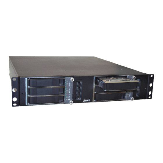
Page 12: Product Components
ArrayMasStor K Series Product Components The K-Series RAID system consists of a RAID controller (SCSI-to-IDE); six IDE drive bays and drive tray assemblies; redundant, hot-swappable power supplies; redundant, hot-swappable fans; and an enclosure to house and integrate these components. RAID Controller The SCSI-to-IDE controller used in the K-Series RAID system is the central element of the product. -
Page 13: Raid Overview
ArrayMasStor K Series RAID Overview Redundant Array of Inexpensive Disks (RAID) is a storage technology used to improve the performance, and increase the reliability, of a data storage system. This technology was developed around the idea of grouping multiple disk drives together (an array) to provide features and functionality thatÕs not available in a single disk drive. -
Page 14: About Raid Levels
ArrayMasStor K Series Since the K-Series RAID system does not support non-RAID storage configurations, a minimum of two disk drives must be installed into the unit. The following section describes each of the RAID levels supported by the system. About RAID levels RAID generally has six common levels (or defined configurations): RAID 0 ~ 5. -
Page 15: Raid 1 (0+1)
ArrayMasStor K Series NOTE: One drawback to RAID 1 is that it does not usually allow run-time expansion. Once a RAID 1 array has been created, to expand it, the data must be backed up elsewhere before new drive(s) can be added. Other RAID levels generally permit run-time expansion. -
Page 16: Spare Drives In Raid Configurations
ArrayMasStor K Series RAID 5 offers increased data transfer rates when data is accessed in large chunks (i.e., sequentially) and reduced data access time for many simultaneous I/OÕs when they do not span more than one drive. Spare drives in RAID configurations RAID implementations include one other basic concept that can be introduced at this point: spare drives. -
Page 17: Removing A Drive From The Raid System (With Power Off)
ArrayMasStor K Series Removing a Drive from the RAID system (with power off) WARNING Ð Unless you are replacing a failed drive, the RAID system should be powered OFF before performing the following procedure. Removing a ÒgoodÓ drive with the... - Page 18 ArrayMasStor K Series WARNING: Be sure that the drive is replaced into the same slot, or bay, that it came from. Mixing up drive positions can result in permanent data loss! Figure 9. Removing a drive tray To remove a ÒFailedÓ drive from the system (with or without power applied), refer to the section titled ÒRemoving a Failed driveÓ.
-
Page 19: Removing A Power Supply From The Raid System (With Power Off)
ArrayMasStor K Series Removing a Power Supply from the RAID system (with power off) WARNING Ð The RAID system must be powered OFF before performing the following procedure. Redundant Power Supplies The K-Series RAID system has two independent, redundant power supplies. Each power supply receives current from the same power cable, and each supply is capable of providing all necessary power to the array and enclosure. - Page 20 ArrayMasStor K Series To reinsert a power supply into the system, carefully slide the power supply into the unit until the locking latch ÒsnapsÓ the power supply into position. The power supply fits snuggly and can require a firm push, at the end of its travel, to engage the securing latch.
-
Page 21: Raid Controller Functions
ArrayMasStor K Series RAID controller functions The LCD Display panel provides a current status readout and complete access to all of the controllerÕs functions and settings. The entire RAID system can be installed, monitored and maintained using only the LCD panel Message Display panel ¯... -
Page 22: Raid Controller Connectors
ArrayMasStor K Series RAID Controller Connectors SCSI Ð These connectors are the main data access buses (or channels) to the RAID system. When NOT chaining with other SCSI devices, an LVD terminator must be placed on one of the connectors. These connectors are pass through connections and are wired in parallel internally. -
Page 23: Using The Raid Controller Functions
ArrayMasStor K Series Using the RAID Controller Functions This section provides a description, and explanation, of the commands and information available via the LCD Display panel. Basic Features The controller firmwareÕs basic features allow you to create, monitor and maintain a RAID array directly via the LCD panel. -
Page 24: Front Panel Configuration Options
ArrayMasStor K Series Disk # Ð displays information about a disk drive, including its × Disk1:Online manufacturer (if known) and its size. Each drive bay will be listed 19569MB regardless of whether or not it has a drive installed. Empty bays will be listed as ÒVacant.Ó... -
Page 25: Auto Raid Setup
ArrayMasStor K Series Auto RAID Setup Auto RAID Setup¯ to start an Auto RAID installation, press the ENTER button. You will be asked to confirm. Use the arrow keys to display your choice and press the ENTER button again. WARNING: Creating a new RAID will destroy all currently stored data If you choose Yes, the display will show a parity initialization percentage. - Page 26 ArrayMasStor K Series To set the SCSI ID on the RAID system, perform the following steps: 1) Make sure that the unit is powered on and ÒReadyÓ. Ready RAID5 2) Press and hold the ÒEXITÓ button on the rear control panel until the...
-
Page 27: Selecting Raid Levels
ArrayMasStor K Series Selecting RAID Levels Advanced users can also use either the Display panel or the terminal emulation utility to manually configure a new RAID array. Step 1 : To use the Display panel to create a new RAID array, press the EXIT button for two seconds to enter the Main Menu. -
Page 28: Troubleshooting
ArrayMasStor K Series Troubleshooting Controller Problems with the controller fall into two categories, serious and disastrous. The controller is the only major component in the K-Series RAID system that can cause a fatal failure on its own. After the system ÒPower On Self TestÓ (POST) is complete, the controller will begin initializing the RAID. -
Page 29: Fans
ArrayMasStor K Series will light. On the power supply itself, the status LED(s) will change from Green to Amber (or extinguish completely), indicating which power supply has failed. Because the unit comes with redundant power supplies, it is possible to replace a failed power supply without powering down or otherwise interrupting data flow. -
Page 30: Drive Trays
ArrayMasStor K Series Drive Trays Drive trays as a component separate from drives are unlikely to encounter problems unrelated to a drive failure. In the event that you suspect a drive failure may in fact be a problem with a drive tray, shut down the host, remove the questionable drive and tray, and examine the power and data cables to see if they have come loose or are damaged. -
Page 31: No Spare Installed
ArrayMasStor K Series NOTE: It is highly recommended that you replace a failed drive even if you already have a spare. An installed spare provides an additional safeguard against future drive failures. No Spare Installed If there is no hot-ready spare drive installed, a single drive failure in a RAID1, RAID3, or RAID5 array will still not result in data loss or downtime. - Page 32 ArrayMasStor K Series The K-Series RAID system can only have one host connected at a Single Host Limitation time. Sharing the array storage capacity is accomplished through the (Important) host OS and hardware, not through the K-Series RAID system. Auto RAID Setup via It is recommend that Auto RAID Setup be used via the LCD display panel to create an array.
-
Page 33: Remote Monitoring And Management
ArrayMasStor K Series Remote Monitoring and Management RS-232C Interface If your data volume is large, it may improve your throughput performance to use a null modem cable for array management. The K-Series RAID system comes with a standard, 9-pin RS-232C serial port, which, using a null modem cable, can be connected to any COM port on a host computer for management purposes. -
Page 34: Adtx Masstor K-Series Specifications
Universal, auto sensing. UL, CSA, TUV approvals. Meets FCC and FTZ regulations. Transfer rates can vary significantly depending upon the HDD. (These specifications are subject to change without notice. Contact ADTX for the latest information and specification updates) (ADTX shall not be responsible for any typographical errors within this document) ÒInstallation Instructions and Procedures.Ó...
Need help?
Do you have a question about the ArrayMasStor K Series and is the answer not in the manual?
Questions and answers