Table of Contents
Advertisement
Advertisement
Table of Contents

Summary of Contents for MKN FlexiChef Series
- Page 1 Read the operating instructions prior to commissioning Installation instructions FlexiChef Unit Energy type Design Model FlexiChef Electric Deep-frying FCEKMP1XXXX-----G2... High-speed cooking FCEKMP3XXXX-----G2... Cleaning FlexiChef Team FCEKMP2XXXX-XXXXG2... 10000008311AINBEB en-GB...
- Page 2 Fax +49 5331 89-280 Internet www.mkn.com Copyright All rights to text, graphics and pictures in this documentation are held by MKN Maschinenfabrik Kurt Neubauer GmbH & Co. KG. Distribution or duplication is only permitted with the prior written consent of MKN.
-
Page 3: Table Of Contents
Directory of contents 1 Introduction ................. 5 1.1 About this manual ................ 5 1.1.1 Explanation of signs .................. 6 1.2 Personnel qualifications .............. 7 1.3 Use of the unit ................... 7 1.4 Warranty .................... 7 2 Safety information .............. 8 3 Description of the unit ............. 11 3.1 Overview of the unit ............... 11 3.2 Equipment identification via order code ... - Page 4 Directory of contents 5.10.1 Securing the unit against sliding ............ 39 6 Connecting the unit ............ 41 6.1 Removing and attaching the cover plate for the service connections .................. 41 6.1.1 Removing the cover plate ................ 41 6.1.2 Attaching the cover plate ................. 41 6.2 Making the electrical connection .......... 42 6.2.1 Description of the power connection ...
-
Page 5: 1 Introduction
Introduction 1 Introduction 1.1 About this manual The instruction manual is part of the unit and contains information on safe installation of the unit. Observe and adhere to the following instructions: • Read the instruction manual in its entirety prior to installation. •... -
Page 6: Explanation Of Signs
Introduction 1.1.1 Explanation of signs DANGER Imminent threat of danger Failure to comply will lead to death or very severe injuries. WARNING Possible threat of danger Failure to comply can lead to death or very severe injuries. CAUTION Dangerous situation Failure to comply can lead to slight or moderately severe injuries. -
Page 7: Personnel Qualifications
Introduction 1.2 Personnel qualifications Explanation of qualification Skilled staff • Skilled staff are those, who due to their profes- sional training, knowledge and experience as well as their knowledge of the relevant standards can assess the tasks given to them and recognize any possible dangers. -
Page 8: 2 Safety Information
Safety information 2 Safety information The unit complies with applicable safety standards. Residual risks associated with operation or risks resulting from incorrect operation cannot be ruled out and are mentioned specifically in the safety instructions and warnings. The installer must be familiar with regional regulations and observe them. - Page 9 Safety information Organisational measures Risk of property damage and personal injury from lack of organizational measures • Identify hazard areas when transporting, setting up and connecting the unit. • Prior to starting the installation work, notify any operators present about the procedure. •...
- Page 10 Safety information Concluding activities Risk of damage to property and personal injury from improper connections • Reactivate all safety devices and check that they function properly. Commissioning Risk of property damage and personal injury from improper commissioning • Read the operating instructions prior to commissioning. Observe the safety instructions in this installation manual and in the "Safety information"...
-
Page 11: 3 Description Of The Unit
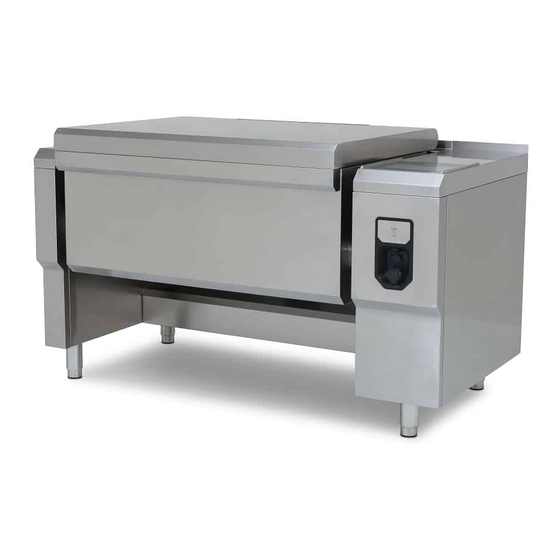
Description of the unit 3 Description of the unit 3.1 Overview of the unit Image: Unit with high-speed cooking and automatic cleaning a Water supply k Steam outlet safety valve (optional) b Lid l Hand shower (optional) c Core temperature sensor m Control unit front panel d Filling nozzle (optional) n Control arm... -
Page 12: Equipment Identification Via Order Code
Description of the unit 3.2 Equipment identification via order code The equipping of the unit can be identified from the order code. The type number with the order code is given on the nameplate. Order code Position Design C = Floor-standing unit I = Suspended unit 1 = Single unit, operation on the right 2 = Team unit, operation in the middle... - Page 13 Description of the unit All models Data interfaces USB port USB 1.0 only for USB flash drives max. 32 GB HACCP RJ45 network cable (CAT5) Bluetooth Power optimizing system Connection terminal (mm²) Floating contact Connection terminal (mm²) Fire protection contact Connection terminal (mm²) Socket Separate supply connection terminal (mm²) Wastewater connection...
- Page 14 Description of the unit Model FCEKMP... Size X12XX... X22XX... X23XX... X32XX... X33XX... Emissions Noise level (db (A)) < 70 Heat output (operation as boiling kettle and cooking appliance) MaxPower, latent / sensible (W) 2940 / 515 4480 / 784 6800 / 1190 FlexPower, latent / sensible (W) 2620 / 459 3440 / 602...
-
Page 15: Basic Control Setting
Description of the unit Model FCEKMP... Size X12XX... X22XX... X23XX... X32XX... X33XX... MaxPower connected load (kW) 15.8 24.2 36.7 MaxPower fuse (A) 3 x 35 3 x 50 3 x 63 Voltage (V) FlexPower connected load (kW) FlexPower fuse (A) MaxPower connected load (kW) 34.9 MaxPower fuse (A) -
Page 16: 4 Transporting The Unit
Transporting the unit 4 Transporting the unit CAUTION Risk of property damage and personnel injury from tipping equipment • Do not linger next to or behind raised equipment. • Move raised equipment carefully. ATTENTION Risk of physical damage from improper transport •... -
Page 17: Removing The Transport Protection
Transporting the unit 4.2 Removing the transport protection Image: Transport protection a Side section c Centre partition b Connecting board d Screw 1. Release and remove the centre partition. 2. Release and remove the connecting board at the front and back. 3. -
Page 18: 5 Setting Up The Unit
Setting up the unit 5 Setting up the unit CAUTION Risk of fire from failure to observe applicable regional fire prevention regulations • Observe applicable regional fire prevention regulations. CAUTION Risk of crushing from improper setup • Protect the unit and work area during setup and alignment. Planning drawing The planning drawing and additional documents are available on the manufacturer's Internet page by entering the equipment number (see... -
Page 19: Minimum Clearances
Setting up the unit 5.1 Minimum clearances Image: Minimum clearance to walls or other units A 400 mm Maintain the clearance between the control arm and walls or protruding units. When emptying by tilting, this gives sufficient clearance between the operator and the food being cooked. -
Page 20: Opening And Closing The Housing
Setting up the unit 5.2 Opening and closing the housing DANGER Risk of personal injury and physical damage from electric shock • Prior to working on the unit, ensure that the unit has been disconnected from the mains. • Do not operate the unit with the housing open. CAUTION Risk of injury from sharp edges •... -
Page 21: Removing And Attaching The Front Panel Of The Control Arm
Setting up the unit 5.2.1 Removing and attaching the front panel of the control arm Image: Removing the front panel of the control arm Removing the front panel of the control arm Requirement Unit is disconnected 1. Undo the screws on the bottom of the front panel. 2. -
Page 22: Removing And Attaching The Cover Of The Control Arm
Setting up the unit 5.2.2 Removing and attaching the cover of the control arm Image: Removing the cover of the control arm a Rear lock b Front lock Removing the cover of the control arm Requirement Unit is disconnected Front panel of the control arm removed 1. -
Page 23: Removing And Attaching The Front Panel Of The Side Arm
Setting up the unit 5.2.3 Removing and attaching the front panel of the side arm Image: Removing the side arm front panel Removing the side arm front panel Requirement Unit is disconnected 1. Unscrew the screw on the bottom of the front panel. 2. -
Page 24: Removing And Attaching The Side Arm Cover
Setting up the unit 5.2.4 Removing and attaching the side arm cover Image: Removing the side arm cover Removing the side arm cover Requirement Front panel of side arm removed 1. Open the rear lock and fix it in position. To do this, pull the lock forwards then press it downwards until it engages. -
Page 25: Opening And Closing The Lid
Setting up the unit 5.2.5 Opening and closing the lid CAUTION Risk of crushing when closing the lid • Keep hands away from the opening and closing area of the lid when closing the lid. ATTENTION Physical damage due to objects slipping The lid opens automatically during the cooking program. - Page 26 Setting up the unit 3. Wait for the lid to reach the end position. The lid is fully open. Closing the lid The unit has a crush protection feature. The lid stops closing when an object is detected between the edge of the unit and the lid.
-
Page 27: Placing The Unit On The Equipment Legs
Setting up the unit 5.3 Placing the unit on the equipment legs WARNING Risk of injury from falling unit • Secure the unit adequately when lifting and lowering. • Do not linger under the unit when lifted. ATTENTION Physical damage from equipment legs shearing off Equipment legs can shear off, if the unit is pushed. -
Page 28: Setting Up The Unit On The Base
Setting up the unit 5.4 Setting up the unit on the base WARNING Risk of injury from falling unit • Secure the unit adequately when lifting and lowering. • Do not linger under the unit when lifted. The equipment legs are enclosed with the unit and must be attached before setting up the unit. -
Page 29: Removing The Transport Securing Device
Setting up the unit 5.5 Removing the transport securing device Image: Removing the transport securing device Requirement Unit in the installation position 1. Pull out the forklift truck. 2. Release the screws on the transport securing device and remove them. 3. -
Page 30: Aligning The Unit On The Base
Setting up the unit 5.6.1 Aligning the unit on the base DANGER Risk of personal injury and physical damage from electric shock • Prior to working on the unit, ensure that the unit has been disconnected from the mains. • Do not operate the unit with the housing open. -
Page 31: Aligning The Unit With Equipment Legs
Setting up the unit 5.6.2 Aligning the unit with equipment legs ATTENTION Physical damage from equipment legs shearing off Equipment legs can shear off, if the unit is pushed. • Do not push the unit. • Raise the unit before moving it. ATTENTION Instability if the equipment legs are screwed out too far Stability no longer assured... -
Page 32: Checking Alignment
Setting up the unit 5.6.3 Checking alignment Image: Checking alignment Requirement Unit is aligned 1. Measure the diagonals between the arms under the pan and compare them. 2. If there is a difference of more than 5 mm mm, correct the alignment. -
Page 33: Setting Up Flexichef Team
Setting up the unit 5.8 Setting up FlexiChef Team 5.8.1 Aligning single units with each other Image: Aligning single units 1. Set up the first unit at the installation site in accordance with the planning drawing (see "Setting up the unit"). 2. -
Page 34: Connecting Single Units To Each Other
Setting up the unit 5.8.2 Connecting single units to each other Image: Connecting single units a Screw c Top connecting plate b Washer d Bottom connecting plate Requirement Single units aligned with each other 1. Attach the top connecting plates at the front and back in accordance with the drawing. -
Page 35: Installing The Control Unit In The Cover
Setting up the unit 5.8.3 Installing the control unit in the cover The control units are supplied separately and must be installed in the cover. Image: Installing the control unit in the cover a Wing screw d Front holding rail b Rear holding rail e Control unit cover c Control unit... -
Page 36: Connecting The Control Unit
Setting up the unit 5.8.4 Connecting the control unit Image: Control unit a USB c Loudspeaker b Network d Control cable Requirement Units connected together 1. Lay the anti-scratch protection on the lid. 2. Lay the control arm cover down on the lid with the sides reversed. Do not mix up the units when connecting the control unit. -
Page 37: Installing The Control Unit Front Panel
Setting up the unit 5.8.5 Installing the control unit front panel Image: Installing the control unit front panel a Control arm cover e Frame b Control unit f Control unit front panel c Hand shower g Water hose d Control arm front panel The control unit front panel is already connected and is ready in the particular unit. -
Page 38: Connecting The Unit
Setting up the unit 5.9 Connecting the unit When setting up with other equipment from the same manufacturer, use end and connecting profiles. Image: Joining the unit a Connecting profile Requirement Cover with discharge channel available Units aligned with each other Attach the connecting profile to the drain channel. -
Page 39: Fastening The Unit To The Floor
Setting up the unit 5.10 Fastening the unit to the floor 5.10.1 Securing the unit against sliding Image: Arrangement of the base plates (view from above) a Equipment leg c FlexiChef b Floor plate d FlexiChef Team A special fastening set with floor plates for securing the unit against sliding is available from the manufacturer as an accessory. - Page 40 Setting up the unit Floor without steam barrier In the case of floors without a steam barrier, the floor plates are screwed to the floor with the enclosed screws. Requirement The floor must be capable of taking the weight of the unit The floor must be clean and suitable for the type of fastening The unit is set up and levelled in accordance with the planning drawing...
-
Page 41: 6 Connecting The Unit
Connecting the unit 6 Connecting the unit 6.1 Removing and attaching the cover plate for the service connections 6.1.1 Removing the cover plate Image: Removing the cover plate a Cover plate b Bolt 1. Press the front edge of the cover plate towards the rear to unlock it, while at the same time lifting it from the side bolts. -
Page 42: Making The Electrical Connection
Connecting the unit 2. Press the front edge of the cover plate towards the rear, while at the same time attaching it to the side bolts. 6.2 Making the electrical connection Electrical installation work Electrical installation work on the electric system and the unit may only be performed by a specialist company, which is approved by the electric utility company in the particular region. - Page 43 Connecting the unit Fault current device Image: RCD switch type A, circuit symbol The unit can be connected to a fault current device. If a fault current device is used, a fault current device type A (RCD type A) must be installed, to ensure that AC fault currents and pulsating DC currents are detected.
-
Page 44: Description Of The Power Connection
Connecting the unit 6.2.1 Description of the power connection DANGER Danger to life from electric shock due to several electrical supply lines In the case of units with a socket, there may be voltage present in the electrical junction box due to a separate supply line. •... -
Page 45: Connecting The Power Connection Cable
Connecting the unit 6.2.2 Connecting the power connection cable DANGER Risk of personal injury and physical damage from electric shock • Before working on the unit, ensure that the unit has been disconnected from the power supply. DANGER Risk of personal injury and physical damage from electric shock •... -
Page 46: Connecting The Socket
Connecting the unit 6.2.3 Connecting the socket DANGER Risk of personal injury and physical damage from electric shock • Before working on the unit, ensure that the unit has been disconnected from the power supply. DANGER Risk of personal injury and physical damage from electric shock •... -
Page 47: Connecting The Power Optimizing System
Connecting the unit 5. Screw on the electrical junction box cover. If necessary, attach the protective conductor. 6. Fill out the commissioning report. 6.2.4 Connecting the power optimizing system DANGER Risk of personal injury and physical damage from electric shock •... -
Page 48: Connecting The Fire Protection Contact
Connecting the unit 2. Feed the connection line into the junction box through the cable gland. 3. Connect the connection line in accordance with the wiring diagram. 4. Firmly tighten the cable gland for strain relief. 5. Screw on the electrical junction box cover. If necessary, attach the protective conductor. -
Page 49: Connecting The Floating Contact
Connecting the unit 6.2.6 Connecting the floating contact DANGER Risk of personal injury and physical damage from electric shock • Before working on the unit, ensure that the unit has been disconnected from the power supply. DANGER Risk of personal injury and physical damage from electric shock •... -
Page 50: Connecting To The Potential Equalisation Circuit
Connecting the unit 6.2.7 Connecting to the potential equalisation circuit Image: Connecting the potential equalisation 1. Run and attach potential equalisation line to the identified terminal. 2. Fill out the commissioning report. 6.3 Performing basic control setting Image: Main menu a Language selection button f "myFavourites"... -
Page 51: Changing The Basic Control Setting
Connecting the unit 6.3.1 Changing the basic control setting The basic settings for operation can be displayed and changed by entering the PIN "111". The basic settings are made in the dialogue. Advanced settings are made via the parameters for the settings. Image: PIN window If an incorrect PIN is entered, access can only be gained to the equipment information in the Equipment settings menu. -
Page 52: Making The Water Connection
Connecting the unit 6.4 Making the water connection Installation work with tap water Installation work on tap water lines and the unit may only be performed by a specialist company, which is approved by the water utility company in the particular region. The applicable regional regulations, standards and guidelines must be observed, as well as the connection conditions imposed by the water utility company responsible. -
Page 53: Connecting The Tap Water Connection Line
Connecting the unit ATTENTION Risk of physical damage from the wrong water quality • Ensure that the water quality complies with the equipment and connection data. ATTENTION Risk of physical damage from dirt particles in the tap water • Ensure that a fine filter with a mesh size < 80 µm is installed in the warm and cold water lines. -
Page 54: Making The Wastewater Connection
Connecting the unit 3. Connect the connection lines in the building to tap water valves using seals. 4. Connect the connection lines (cold and warm) to the unit. 5. Open the tap water valves and check the threaded connectors for leaks. -
Page 55: Connecting The Wastewater Line To A Permanent Connection
Connecting the unit 6.5.1 Connecting the wastewater line to a permanent connection Image: Wastewater line to a permanent connection a Wastewater connection c Wastewater system b Wastewater line Requirement Pipe lines comply with specifications (see "Equipment and connection data") Cover plate for service connections removed 1. -
Page 56: Connecting The Wastewater Connection To A Waste Trap In The Building
Connecting the unit 6.5.2 Connecting the wastewater connection to a waste trap in the building ATTENTION Risk of water escape if there is backing up in the wastewater pipe The water height within the waste trap must not be more than 50 mm mm. -
Page 57: Connecting A Wastewater Line With An Unobstructed Discharge
Connecting the unit 6.5.3 Connecting a wastewater line with an unobstructed discharge The wastewater line must end at least 20 mm above the floor gutter. Image: Connection with unobstructed discharge a Wastewater connection c Floor gutter b Wastewater line d Wastewater system Requirement Pipe lines comply with specifications (see "Equipment and connection data") Cover plate for service connections removed... -
Page 58: 7 Checking Operation
Checking operation 7 Checking operation DANGER Risk of personal injury and physical damage from unsuccessful operational check • Do not put the unit into service. • Contact customer service. DANGER Risk of personal injury and physical damage from electric shock •... -
Page 59: Checking The Lid
Checking operation Image: Checking the pan position 7.2 Checking the lid Requirement Diagonals checked 1. Open and close the lid (see "Opening and closing the lid") 2. Check whether the lid opens and closes properly. If the lid makes a noise or jerks, check the alignment. 3. -
Page 60: Checking The Water Inlet
Checking operation 7.4 Checking the water inlet 1. Press the On Off ("I O") switch to "I". The Main menu is displayed. 2. Tap the "Equipment functions" button. 3. Tap the "Water inlet" field. 4. Set the water inlet to "Warm water". 5. -
Page 61: 8 Putting The Unit Into Service
Requirement Power connection made Housing closed Operation successfully tested 1. Instruct the operator. 2. Fill out the commissioning report. 8.1 Nameplate MKN Maschinenfabrik Kurt Neubauer GmbH & Co. KG, Halberstädter Str. 2a, D-38300 Wolfenbüttel Typ: Item-Nr.: Bez.: ... - Page 62 Putting the unit into service General information FlexiChef Team connected and fixed? FlexiChef Team control unit connected? FlexiChef Team control unit installed in control arm front panel? General information Unit fastened to the floor? Secured against tilting Secured against sliding Floor screw fitting Floor screw fitting Floor bonding...
- Page 63 Putting the unit into service Function check Controls are functioning? Does tilting function? Does lid opening and closing function? Wastewater drains away without backing up? Water inlet checked? Does the water jet hit the edge of the pan? Perlator used? Final notes Was the unit put into service? Comments:...
- Page 64 Putting the unit into service Installation instructions...
- Page 68 www.mkn.com...
Need help?
Do you have a question about the FlexiChef Series and is the answer not in the manual?
Questions and answers