Table of Contents
Advertisement
Quick Links
MS202E
H-850 Hexapod Microrobot
User Manual
Version: 2.3.0
Physik Instrumente (PI) GmbH & Co. KG, Auf der Roemerstrasse 1, 76228 Karlsruhe, Germany
Phone +49 721 4846-0, Fax +49 721 4846-1019, Email info@pi.ws, www.pi.ws
Date: 03.12.2019
This document describes the following hexapod
microrobots:
H-850.H2
H-850.H2A
H-850.H2I
H-850.H2V
H-850.G2
H-850.G2A
H-850.G2I
H-850.G2V
Advertisement
Table of Contents

Summary of Contents for Physik Instrumente H-850 Series
- Page 1 H-850.H2A H-850.H2I H-850.H2V H-850.G2 H-850.G2A H-850.G2I H-850.G2V Physik Instrumente (PI) GmbH & Co. KG, Auf der Roemerstrasse 1, 76228 Karlsruhe, Germany Phone +49 721 4846-0, Fax +49 721 4846-1019, Email info@pi.ws, www.pi.ws...
- Page 2 BiSS is a registered trademark of iC-Haus GmbH. © 2019 Physik Instrumente (PI) GmbH & Co. KG, Karlsruhe, Germany. The text, photographs, and drawings in this manual are protected by copyright. With regard thereto, Physik Instrumente (PI) GmbH & Co. KG retains all the rights.
-
Page 3: Table Of Contents
Contents About this Document Objective and Target Audience of this User Manual..........1 Symbols and Typographic Conventions..............1 Figures ........................2 Other Applicable Documents ..................2 Downloading Manuals ....................3 Safety Intended Use ......................5 General Safety Instructions ..................5 Organizational Measures .................... - Page 4 Mounting the Hexapod on a Surface ............... 26 Fixing the Load to the Hexapod ................28 Optional: Removing the Coordinate Cube ............... 29 Connecting the Hexapod to the Controller .............. 30 Startup General Notes on Startup ..................37 Starting Up the Hexapod System ................38 Baking Out Vacuum-Compatible Models ..............
-
Page 5: About This Document
1 About this Document About this Document In this Chapter Objective and Target Audience of this User Manual ..............1 Symbols and Typographic Conventions ..................1 Figures ............................2 Other Applicable Documents ......................2 Downloading Manuals ........................3 Objective and Target Audience of this User Manual This manual contains information on using the H-850 as intended. -
Page 6: Figures
1 About this Document Symbol/Label Meaning Action consisting of several steps whose sequential order must be observed Action consisting of one or several steps whose sequential order is irrelevant List item p. 5 Cross-reference to page 5 RS-232 Labeling of an operating element on the product (example: socket of the RS-232 interface) Warning sign on the product which refers to detailed information in this... -
Page 7: Downloading Manuals
1 About this Document Downloading Manuals INFORMATION If a manual is missing or problems occur with downloading: Contact our customer service department (p. 53). Downloading manuals 1. Open the website www.pi.ws. 2. Search the website for the product number (e.g., P-882) or the product family (e.g., PICMA®... -
Page 9: Safety
2 Safety Safety In this Chapter Intended Use ..........................5 General Safety Instructions......................5 Organizational Measures ....................... 5 Measures for Handling Vacuum-Compatible Products ..............6 Intended Use The hexapod microrobot (short "hexapod") is a laboratory device as defined by DIN EN 61010-1. It is built for indoor use and use in an environment which is free of dirt, oil, and lubricants. -
Page 10: Measures For Handling Vacuum-Compatible Products
2 Safety Add all information from the manufacturer to the user manual, for example supplements or technical notes. If you give the H-850 to a third party, include this user manual as well as other relevant information provided by the manufacturer. ... -
Page 11: Product Description
3 Product Description Product Description In this Chapter Features and Applications ......................7 Model Overview ..........................7 Suitable Controllers ........................8 Product View ..........................9 Scope of Delivery ........................... 9 Accessories ........................... 10 Technical Features ........................12 Features and Applications The various models (p. -
Page 12: Suitable Controllers
3 Product Description Model Designation H-850.H2V Precision Hexapod microrobot, DC gear motor, rotary encoder, 80 kg load capacity, 0.15 mm/s velocity, vacuum compatible to 10 hPa, including 3 m cable set on the air side and 2 m cable set on the vacuum side H-850.G2 Precision Hexapod microrobot, DC gear motor, rotary encoder, 50 kg load capacity, 8 mm/s velocity, including 3 m cable... -
Page 13: Product View
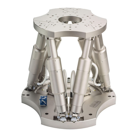
3 Product Description Product View Figure 1: Product view, here: H-850.G2A Panel plug for data transmission cable Panel plug for power supply cable Motion platform Strut Coordinate cube Base plate Scope of Delivery Order number Components H-850 Hexapod according to your order (p. 7) 000015165 Snap-on ferrite Cable set for all H-850 models:... -
Page 14: Accessories
3 Product Description Order number Components Additional cable set for all vacuum-compatible models (H-850.H2V, H-850.G2V): K040B0254 Data transmission cable on the vacuum side, HD D-sub 78 m/f, 1:1, 2 m 4668 Vacuum feedthrough for data transmission, HD D-sub 78 m/f K060B0132 Power supply cable on the vacuum side, LEMO 2-pin (m) 180°... - Page 15 3 Product Description Order number Description* C-887.5A05 Hexapod cable set 5 m, consisting of: Designation Length Item number Data transmission cable, HD D-sub 78 f/m, 1:1 K040B0243 Power supply cable, M12 m/f, 1:1 K060B0222 C-887.5B05 Hexapod cable set 5 m, drag chain compatible, consisting of: Designation Length Item number...
-
Page 16: Technical Features
3 Product Description Order number Description* C-887.5A50 Hexapod cable set 50 m, consisting of: Designation Length Item number Line driver box for data transmission cable, – C887B0057 controller-side Line driver box for data transmission cable, – C887B0058 hexapod-side Short data transmission cable, HD D-sub 78 f/m, K040B0241 Long data transmission cable, HD D-sub 44 f/m, 44 m... -
Page 17: Reference Switch And Limit Switches
3 Product Description 3.7.2 Reference Switch and Limit Switches The reference switch of a strut functions independently of the angular positions of the strut ends and the lengths of the other struts. When a limit switch is activated, the power source of the motor is switched off to protect the hexapod against damage from malfunctions. - Page 18 3 Product Description The following is a description of how the hexapod behaves with the default coordinate system. Work with user-defined coordinate systems is described in the C887T0007 technical note. Figure 2: Coordinate system and rotations to the rotational coordinates U, V, and W. The coordinate system is depicted above the platform for better clarity.
- Page 19 3 Product Description Example: Consecutive rotations INFORMATION For a clearer view, the figures have been adapted as follows: Round platform replaced by T-shaped platform Coordinate system shown shifted Center of rotation in the top left corner of the platform 1.
- Page 20 3 Product Description 2. The V axis is commanded to move to position –10. The rotation takes place around rotational axis V, which was tilted during the previous rotation. The rotation around the V axis tilts the rotational axes U and W. Figure 4: Rotation around the V axis Platform in reference position...
-
Page 21: Id Chip
3 Product Description 3. The W axis is commanded to move to position 10. The rotation takes place around the rotational axis W, which was tilted during the previous rotations. The W axis is always vertical to the platform level. The rotation around the W axis tilts the rotational axes U and V. -
Page 23: Unpacking
4 Unpacking Unpacking The hexapod is delivered in a special packaging with adapted foam inserts and with a transport safeguard attached. NOTICE Impermissible mechanical load! An impermissible mechanical load can damage the hexapod. Only send the hexapod in the original packaging. ... -
Page 24: Removing The Transport Safeguard
4 Unpacking Removing the Transport Safeguard 4.2.1 Removing the Transport Safeguard for the H-850.x2 and .x2V Models Figure 6: Transport safeguard for the H-850.x2 and .x2V hexapod models Hexapod with transport safeguard attached Transport safeguard with fixing screws Tools and accessories Hex key 5.0 from the screw set (p. -
Page 25: Removing The Transport Safeguard For The H-850.X2A And .X2I Models
4 Unpacking 4.2.2 Removing the Transport Safeguard for the H-850.x2A and .x2I Models Figure 7: H-850.x2A and .x2I models: Transport safeguard components Cover M6x16 screw M8 nut Strut Tools and accessories Open-end wrench AF 10 Open-end wrench AF 13 ... -
Page 27: Installation
5 Installation Installation In this Chapter General Notes on Installation ...................... 23 Determining the Permissible Load and Workspace ..............24 Attaching the Snap-on Ferrite...................... 25 Grounding the Hexapod ....................... 26 Mounting the Hexapod on a Surface ................... 26 Fixing the Load to the Hexapod ....................28 Optional: Removing the Coordinate Cube ................... -
Page 28: Determining The Permissible Load And Workspace
5 Installation INFORMATION The optionally available PIVeriMove hexapod software for collision checking makes it possible to check mathematically for possible collisions between the hexapod, load, and surroundings. The use of the software is recommended when the hexapod is located in a limited installation space and/or operated with a spatially limiting load. -
Page 29: Attaching The Snap-On Ferrite
5 Installation Attaching the Snap-on Ferrite Figure 8: Power supply cable of the hexapod with snap-on ferrite Power supply cable of the hexapod 000015165 snap-on ferrite M12 connector (m) (for connection to the controller) INFORMATION The snap-on ferrite ensures the electromagnetic compatibility of the hexapod system. 000015165 snap-on ferrite: The 000015165 snap-on ferrite is included in the scope of delivery of the hexapod. -
Page 30: Grounding The Hexapod
5 Installation Permanently attaching the snap-on ferrite 1. 000015165 snap-on ferrite: Put the power supply cable of the hexapod into the open snap-on ferrite close to and behind the M12 connector (m) that is intended for connection to the controller (see figure). - Page 31 5 Installation NOTICE Warping of the base plate! Incorrect mounting can warp the base plate. Warping of the base plate reduces the accuracy. Mount the hexapod on an even surface. The recommended flatness of the surface is 300 µm. Requirements ...
-
Page 32: Fixing The Load To The Hexapod
5 Installation Fixing the Load to the Hexapod NOTICE Impermissible mechanical load and collisions! Impermissible mechanical load and collisions between the hexapod, the load to be moved, and the surroundings can damage the hexapod. Make sure that the installed load observes the limit value resulting from the load test (p. -
Page 33: Optional: Removing The Coordinate Cube
5 Installation Fixing the load 1. Align the load so that the selected mounting holes in the motion platform can be used to fix it. If you use locating pins to align the load: a) Drill two locating holes into the load to accommodate the locating pins. b) Insert the locating pins into the locating holes in the motion platform or in the load. -
Page 34: Connecting The Hexapod To The Controller
5 Installation Connecting the Hexapod to the Controller A cable set with a length of 3 m is included in the scope of delivery of the hexapod (p. 9). Additional cable sets are available as optional accessory (p. 10). Cable sets with a length >20 m include line driver boxes (e.g., C-887.5A50 cable set with a length of 50 m). - Page 35 5 Installation If necessary: Installing vacuum feedthroughs Figure 10: Vacuum feedthrough for data transmission (4668), dimensions in mm 4 holes, Ø6 x 45° for M3 countersunk screw Install the vacuum feedthrough for data transmission (4668) so that the HD Sub-D 78 socket (f) is in the vacuum chamber.
- Page 36 5 Installation Figure 11: Vacuum feedthrough for the power supply of the hexapod (C887B0002), dimensions in mm Install the vacuum feedthrough for the power supply (C887B0002) so that the 2-pin LEMO connection is in the vacuum chamber. Connecting the hexapod to the controller ...
- Page 37 5 Installation Standard cabling (no vacuum, without line driver boxes) Figure 12: Connection diagram of cable set without line driver boxes Panel plug / connector, male Socket / connector, female Controller Refer to "Suitable Controllers" (p. 8) Hexapod H-850.H2, .H2A, .H2I, .G2, .G2A, .G2I Power adapter, from the scope of delivery of the controller, 24 V DC output Data transmission cable* Power supply cable*...
- Page 38 5 Installation Cabling with line driver boxes (no vacuum) Figure 13: Connection diagram of cable set with line driver boxes Panel plug / connector, male Socket / connector, female Controller Refer to "Suitable Controllers" (p. 8) Hexapod H-850.H2, .H2A, .H2I, .G2, .G2A, .G2I Controller-side line driver box* Hexapod-side line driver box* Power adapter, 24 V DC output*...
- Page 39 5 Installation Cabling for vacuum (without line driver boxes) Figure 14: Connection diagram of the cable set for the vacuum-compatible hexapod Panel plug / connector, male Socket / connector, female Controller Refer to "Suitable Controllers" (p. 8) Hexapod H-850.H2V, .G2V Power adapter, from the scope of delivery of the controller, 24 V DC output Vacuum chamber Data transmission cable*...
-
Page 41: Startup
6 Startup Startup In this Chapter General Notes on Startup ......................37 Starting Up the Hexapod System ....................38 Baking Out Vacuum-Compatible Models ..................39 General Notes on Startup CAUTION Risk of crushing by moving parts! There is a risk of minor injuries from crushing between the moving parts of the hexapod and a stationary part or obstacle. -
Page 42: Starting Up The Hexapod System
6 Startup NOTICE Damage due to collisions! Collisions can damage the hexapod, the load to be moved, and the surroundings. Make sure that no collisions are possible between the hexapod, the load to be moved, and the surroundings in the workspace of the hexapod. ... -
Page 43: Baking Out Vacuum-Compatible Models
6 Startup Baking Out Vacuum-Compatible Models NOTICE Failure of the hexapod! The lubricant in the drivetrain can be spread unevenly during the bakeout and cooling process of the hexapod. Uneven distribution of the lubricant can lead to failure of the hexapod. Maintenance runs that are performed over the entire travel range of the hexapod struts during the bakeout and cooling process cause the lubricant to spread evenly again. -
Page 45: Maintenance
7 Maintenance Maintenance In this Chapter Performing a Maintenance Run ....................41 Packing the Hexapod for Transport ..................... 41 Cleaning the Hexapod ........................49 NOTICE Damage due to improper maintenance! The hexapod can become misaligned as a result of improper maintenance. The specifications can change as a result (p. -
Page 46: Attaching The Transport Safeguard
7 Maintenance Accessories Transport safeguard (p. 19) Original packaging (p. 9) Electrostatic dissipative film Strapping tape Stretch film 7.2.1 Attaching the Transport Safeguard Attaching the transport safeguard for the H-850.x2 and .x2V models 1. Command motion of the hexapod to the transport position: X = Y = U = V = 0 Z = -23 W = -6... - Page 47 7 Maintenance 3. Position the transport safeguard (1) on the hexapod so that the holes in the struts of the transport safeguard are in line with the corresponding holes in the motion platform (2) and the base plate of the hexapod (see figures in "Removing the Transport Safeguard for the H-850.x2 and .x2V Models"...
- Page 48 7 Maintenance 3. Secure the transport safeguard: Screw in the struts of the transport safeguard: a) Screw the struts with the shorter thread into the hexapod's base plate as shown in the figure. b) Tighten the struts by hand. Securing nuts and flat washers: a) Screw an M8 nut onto each strut up to the end of the thread.
- Page 49 7 Maintenance Attaching the cover to the motion platform a) Put the cover onto the motion platform so that the ends of the 4 struts protrude through the corresponding holes in the cover. b) Attach the cover to the motion platform using the four M6x16 screws that you previously pushed a 6.4 flat washer onto.
-
Page 50: Packing The Hexapod
7 Maintenance Securing the cover with counternuts: a) Lock each nut above and below the cover for each strut. b) Put thread protection caps onto the strut ends. Installation is now complete 7.2.2 Packing the Hexapod Packing the hexapod 1. Attach the transport safeguard to the hexapod. Follow the instructions (p. 42). 2. - Page 51 7 Maintenance 5. Put the foam cover onto the hexapod, see figure. Pay attention to the appropriate orientation of the cover. 6. If a folded corrugated cardboard cushion is part of the original packaging: Place the cushion onto the foam cover, see figure. 7.
- Page 52 7 Maintenance Step 6 Only necessary when a cushion made of folded corrugated cardboard is part of the original packaging. Step 8 Step 9 Step 11 The upper box contains the controller. Version: 2.3.0 MS202E H-850 Hexapod Microrobot...
-
Page 53: Cleaning The Hexapod
7 Maintenance Cleaning the Hexapod Requirements You have removed the cables for data transmission and the power supply from the hexapod. Cleaning the hexapod Only when the hexapod is not used in vacuum: If necessary, clean the surfaces of the hexapod with a cloth that is dampened with a mild cleanser or disinfectant. -
Page 55: Troubleshooting
8 Troubleshooting Troubleshooting Problem Possible causes Solution Unexpected hexapod Check the data transmission and Cable defective behavior. power supply cables. Connector or soldered Replace the cables by cables of the joints loosened same type and test the function of the hexapod. - Page 56 8 Troubleshooting Problem Possible causes Solution 2. Activate the 24 V Out 7 A output with "Make contact" (for details, see user manual for the controller). If you use the C-887.MSB motion- stop-box from PI: Press the mushroom button first to unlock it, then press the green pushbutton.
-
Page 57: Customer Service
9 Customer Service Customer Service For inquiries and orders, contact your PI sales engineer or send us an email (mailto:service@pi.de). If you have any questions concerning your system, provide the following information: − Product and serial numbers of all products in the system −... -
Page 59: Technical Data
10 Technical Data Technical Data In this Chapter Specifications ..........................55 Cable Set Specifications ....................... 60 Ambient Conditions and Classifications ..................61 Dimensions ..........................61 Pin Assignment ..........................63 10.1 Specifications 10.1.1 Data Table Motion and positioning H-850.H2A H-850.G2A H-850.H2I H-850.G2I Unit Tole-... - Page 60 10 Technical Data Motion and positioning H-850.H2A H-850.G2A H-850.H2I H-850.G2I Unit Tole- rance Repeatability in Z ±0.2 ±0.2 ±0.2 ±0.2 µm typ. Repeatability in θ , θ ±3 ±3 ±3 ±3 µrad typ. Repeatability in θ ±9 ±7.5 ±9 ±7.5 µrad typ.
- Page 61 10 Technical Data Motion and positioning H-850.H2 / H2V** H-850.G2 / G2V** Unit Tolerance Active axes X, Y, Z, θ , θ , θ X, Y, Z, θ , θ , θ Travel range* X, Y ±50 ±50 Travel range* Z ±25 ±25 Travel range* θ...
-
Page 62: Specifications For Vacuum-Compatible Versions
10 Technical Data Mechanical properties H-850.H2 / H2V** H-850.G2 / G2V** Unit Tolerance Holding force, power off, base max. plate in any orientation Motor Type DC gear motor DC gear motor Miscellaneous H-850.H2 / H2V** H-850.G2 / G2V** Unit Tolerance Operating temperature range -10 to 50 -10 to 50... - Page 63 10 Technical Data H-850.H2V H-850.G2V Unit Tolerance Mechanical properties Load capacity (horizontal base plate / 80 / 40 25 / 10 max. any orientation) 2000 / 400 250 / 85 max. Holding force (base plate horizontal / any orientation) Miscellaneous Cable length 2 m on the vacuum 2 m on the vacuum...
-
Page 64: Maximum Ratings
10 Technical Data 10.1.3 Maximum Ratings The hexapod is designed for the following operating data: Maximum Maximum Maximum operating operating current frequency voltage consumption (unloaded) 24 V DC 10.2 Cable Set Specifications The following table lists the technical data of all optionally available cable sets, irrespective of whether they are suitable for the H-850 hexapods. -
Page 65: Ambient Conditions And Classifications
10 Technical Data 10.3 Ambient Conditions and Classifications Degree of pollution: Air pressure 1100 hPa to 780 hPa Vacuum-compatible models: 1100 hPa to 10 Transport temperature: –25 °C to +85 °C Storage temperature: 0 °C to 70 °C Bakeout temperature Vacuum-compatible models only: 80 °C (176 °F) Humidity:... - Page 66 10 Technical Data Figure 18: H-850.H2A, .H2I, .G2A, .G2I hexapod models (dimensions in mm) Version: 2.3.0 MS202E H-850 Hexapod Microrobot...
-
Page 67: Pin Assignment
10 Technical Data 10.5 Pin Assignment 10.5.1 Power Supply Connection Not for vacuum versions: Power supply via 4-pin M12 Panel plug Function 24 V DC 24 V DC Only for vacuum versions: power supply via 2-pin LEMO panel plug, male, type ECJ.1B.302.CLD Function 24 V DC 10.5.2... - Page 68 10 Technical Data Signal Signal CH1 A+ OUT CH1 B+ OUT CH1 A- OUT CH1 B- OUT CH2 Sign IN CH2 MAGN IN CH2 Ref OUT CH2 LimP OUT CH2 LimN OUT CH2 A+ OUT CH2 B+ OUT CH2 A- OUT CH2 B- OUT CH3 Sign IN CH3 MAGN IN...
- Page 69 10 Technical Data Signal Signal CH6 A- OUT CH6 B- OUT ID Chip Brake/Enable drive 24 V input Power Good 24 V output H-850 Hexapod Microrobot MS202E Version: 2.3.0...
-
Page 71: Old Equipment Disposal
Dispose of your old equipment according to international, national, and local rules and regulations. In order to fulfil its responsibility as the product manufacturer, Physik Instrumente (PI) GmbH & Co. KG undertakes environmentally correct disposal of all old PI equipment made available on the market after 13 August 2005 without charge. -
Page 73: Glossary
12 Glossary Glossary User-defined coordinate system Using the controller, custom coordinate systems can be defined and used instead of the default coordinate systems. Work with user-defined coordinate systems and the work-and-tool concept is described in the C887T0007 technical note. Workspace The entirety of all combinations of translations and rotations that the hexapod can approach from the current position is referred to as the workspace. - Page 74 12 Glossary The Z axis is perpendicular to the base plate of the hexapod. The following example figures of the H-810 hexapod show that the coordinate system does not move along with motion of the platform. Figure 19: H-810 hexapod in the reference position. Cable exit Version: 2.3.0 MS202E...
- Page 75 12 Glossary Figure 20: H-810 hexapod, the platform of which has been moved in X. Cable exit H-850 Hexapod Microrobot MS202E Version: 2.3.0...
-
Page 77: Appendix
13 Appendix Appendix In this Chapter Explanations of the Performance Test Sheet ................73 EU Declaration of Conformity ...................... 75 13.1 Explanations of the Performance Test Sheet The hexapod is tested for the positioning accuracy of the translational axes before delivery. The performance test sheet is included in the scope of delivery. -
Page 79: Eu Declaration Of Conformity
13 Appendix 13.2 EU Declaration of Conformity For the H-850, an EU Declaration of Conformity has been issued in accordance with the following European directives: EMC Directive RoHS Directive The applied standards certifying the conformity are listed below. EMC: EN 61326-1 Safety: EN 61010-1 RoHS: EN 50581 H-850 Hexapod Microrobot...
Need help?
Do you have a question about the H-850 Series and is the answer not in the manual?
Questions and answers