Table of Contents

Related Manuals for APG DCR-1006A

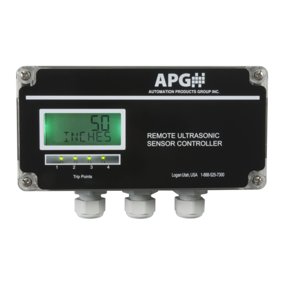
Summary of Contents for APG DCR-1006A
- Page 1 AUTOMATION P R O D U C T S GROUP, INC. Operator’s Manual DCR-1006A Level Controller Rev. B2 (7/15) DOC 9004120 Automation Products Group, Inc. Tel: 1/888/525-7300 • Fax: 1/435/753-7490 • www.apgsensors.com • E-mail: sales@apgsensors.com...
-
Page 2: Table Of Contents
Warranty ..................3 Understanding Ultrasonics ............4-5 Installation ................... 6-8 Wiring ..................9-13 DCR-1006A Terminals ..............9 Powering the DCR-1006A ............9 Sensor Wiring ................10 RST Module Wiring ..............10 4-20mA Wiring ................11 Switched Input/Relay Wiring ..........12-13 Programming ................ -
Page 3: Warranty
No representation or warranty, express or implied, made by any sales representative, distributor, or other agent or representative of APG which is not specifically set forth herein shall be binding upon APG. APG shall not be liable for any incidental or consequential damages, losses or expenses directly or indirectly arising from the sale, handling, improper application or use of the goods or from any other cause relating thereto and APG’s liability hereunder, in... -
Page 4: Understanding Ultrasonics
DCR-1006A Level Controller Rev. B2, 7/15 • Understanding Ultrasonics Ultrasonic sensors use a transducer to transmit bursts of ultrasonic sound waves. Each burst contains a series of pulsed sound waves that emit in the shape of a cone, reflect off the target, and are detected by the sensor. The time required for the sound waves to travel to and from the target is converted into a distance measurement by the sensor. - Page 5 Environmental Conditions Temperature, humidity, vapors, dust, and pressure can affect the sensor’s performance. APG ultrasonic sensors are designed to compensate for many of these conditions. However, if the conditions are extreme, sensor performance can be degraded enough to require the use of a longer-range sensor than normal conditions would require.
-
Page 6: Installation
DCR-1006A Level Controller Rev. B2, 7/15 • Installation Proper sensor mounting is critical for successful operation of an ultrasonic sensor. Using the following guidelines can help ensure trouble free installation and operation: • Ensure that the sensor face is perpendicular to the target surface. If the target is more than a few degrees off perpendicular, it may not be detected. - Page 7 Rev. B2, 7/15 DCR-1006A Level Controller • Always mount above the highest anticipated target level by at least the published minimum blanking distance. If a target enters into the blanking area, error in the detection will occur. It is always advisable to allow for sufficient headroom to ensure that the target does not enter the blanking area.
- Page 8 DCR-1006A Level Controller Rev. B2, 7/15 Stand Pipe Mounting Stand pipes are used to provide headroom at the top of a tank when the target is expected to come closer to the sensor than the minimum blanking distance. It’s very critical that the stand pipe be installed perpendicular to the target.
-
Page 9: Wiring
SENSOR INPUT 85-264 VAC 120-370 VDC AC/N (-) AC/L (+) Powering the DCR-1006A Power to the DCR-1006A can be supplied from either 85-264 VAC or 12-24 VDC. DC Voltage Powered Powering with AC Voltage 85-264 VAC INPUT Ground AC/N (-) -
Page 10: Sensor Wiring
DCR-1006A Level Controller Rev. B2, 7/15 Sensor Wiring The DCR-1006A is compatible with most DST, MNU, and MPX series sensors. MNU/MPX Standard Cable Micro-Connector MNU or MPX Sensor Pin 1 (Brown) Black Pin 3 (Blue) White Pin 2 (White) Green... -
Page 11: 4-20Ma Wiring
The 4-20mA output runs on an independent isolated circuit that must be sup- plied 9-28 VDC in order to operate. The source voltage (Vs) can be supplied from the 24 VDC source on the DCR-1006A, or from an external power source in an isolated circuit as shown below. -
Page 12: Switched Input/Relay Wiring
DCR-1006A Level Controller Rev. B2, 7/15 Wiring the Switched Input for High/Low Level Backup The DCR’s Switched Input can be connected to simple switching device, such as a float switch, to provide a high/low level backup and prevent dry pumping or overflow conditions in the event of an ultrasonic sensor failure or malfunction. - Page 13 Rev. B2, 7/15 DCR-1006A Level Controller Normally Closed Switched Input (Start Prevention) Trip 1 (NO) is controlled by the sensor Relay Controlling Pump/Valve, (see Relay Trip Types and Relay Logic Switched Controlled Relay Controlled Input by Sensor by Switch Input Diagrams on pages 32-33), closing for ON conditions.
-
Page 14: Programming
DCR-1006A Level Controller Rev. B2, 7/15 • Programming The DCR-1006A can be programmed using the on-board push buttons or by using the RS-485 NET interface to communicate with APG’s Modbus software or RST-5003 communications module. Push Button Functions: ENTER Opens the programming menu, selects menu options, accepts parameter set- tings, and steps left one digit within any numeric settings. - Page 15 Rev. B2, 7/15 DCR-1006A Level Controller Upper Level Menu Structure SENSIT UNITS RESET bACK L MAXdIS CUSTOM OFFSET bASIC VOLUNI MULTIP IN SEL T-COMP dECIML ULTRA SAMP R SENS N OUTRAN WINdOW TRIP3W AVERAG TRIP3V GAIN C TRIP2T bLANK TRIP2W...
-
Page 16: Basic Parameters
DCR-1006A Level Controller Rev. B2, 7/15 bASIC • (Basic Parameters) UNITS inches, feet, meters bACK L 0, 1, 2, 3, 4, 5, 6, 7, 8 back light CUSTOM 6-digit alpha-numeric custom units bASIC VOLUNI , Mft , Gallons, m , Liters, in... - Page 17 LR DST: Long Range DST (DST-3434) RS485: (MNU or MPX sensors only) NOTE: when connecting a new RS-485 sensor to the DCR-1006A, set the Input Select to DST (with the new RS-485 sensor connected), then switch the Input Select to RS485. This will initiate the DCR-1006A to upload and configure the parameter settings in the RS-485 sensor for proper operation with the DCR- 1006A.
-
Page 18: Ultrasonic Parameters
DCR-1006A Level Controller Rev. B2, 7/15 ULTRA • (Ultrasonic Sensor Parameters) SENSIT 0 to 100 sensitivity PULSES 0 to 20 pulses bLANK 0 to Max. blanking GAIN C Manual, Auto, *Hard, *Soft, *Auto Soft gain control *Available with MNU sensors only... - Page 19 Rev. B2, 7/15 DCR-1006A Level Controller SENSIT (Sensitivity): Controls the level of amplification applied the returning target echoes (signals). The sensitivity setting is expressed as a percentage: 0 to 100%. PULSES: Controls the number of sound wave pulses sent in each ultrasonic burst. The greater the number of pulses, the stronger the transmitted signal.
- Page 20 DCR-1006A Level Controller Rev. B2, 7/15 MAXdIS (Maximum Distance): Sets the distance (in the selected Units), beginning at the sensor face, to the point where the sensor will stop looking for target echoes. Targets detected beyond the Maximum Distance will be ignored.
- Page 21 Rev. B2, 7/15 DCR-1006A Level Controller T-COMP (Temperature Compensation): Used to enable or disable the internal temperature compensation of the sen- sor. Enabling the internal temperature compensation can reduce the effects of temperature changes by 50% or more, depending on the temperature gradient through the sensing range.
-
Page 22: Application Types
APP TY • Application Types The DCR-1006A has 11 Application Type operating modes to convert the meas- urement to the target into a calculated reading, such as a tank volume. Refer to the following section for a descriptions and settings. - Page 23 Rev. B2, 7/15 DCR-1006A Level Controller Full Distance 000000 Empty Distance 000000 HCSPHE Diameter 000000 horizontal cylinder Length 000000 000000 End Radius Full Distance 000000 SPHERI 000000 Empty Distance spherical 000000 Diameter Full Distance 000000 L CALC Empty Distance 000000...
- Page 24 DCR-1006A Level Controller Rev. B2, 7/15 dIST (Distance to Target) Displays the distance to the target in the selected Units. Distance LEVEL (Depth of Level) Displays the depth of level in the selected Units. Parameters: FULL d (Full Distance) Level...
- Page 25 Rev. B2, 7/15 DCR-1006A Level Controller SCCbOT (Standing Cylinder with Conical Bottom) Parameters: Diameter FULL d (Full Distance) Full EMPTYd (Empty Distance) Distance dIAMET (Tank Diameter) CONE L (Cone Length) CONE d (Cone Diameter) Empty Distance Cone Length Cone Diameter...
- Page 26 DCR-1006A Level Controller Rev. B2, 7/15 HCSPHE (Horizontal Cylinder with Hemispherical Ends) Parameters: FULL d (Full Distance) Full Distance EMPTYd (Empty Distance) Empty Diameter Distance LENGTH (Tank Length) Radius dIAMET (Tank Diameter) Length *ENd RA (End Radius) *set to 0 for flat ended tanks.
- Page 27 Rev. B2, 7/15 DCR-1006A Level Controller VERTOV (Vertical Oval) Parameters: Full Distance FULL d (Full Distance) EMPTYd (Empty Distance) LENGTH (Tank Length) Depth Empty Distance DEPTH (Tank Depth) WIDTH (Tank Width) Length HORTOV (Horizontal Oval) Parameters: FULL d (Full Distance)
- Page 28 Allows the sensor to mimic a tank strapping chart by using a 3rd degree polyno- mial equation to produce a “curve fit” approximation. NOTE: The 4 coefficient values must be entered using the APG Modbus soft- ware, via an RST-6001 module. Refer to the instructions below to enter Curve Fit data.
- Page 29 Rev. B2, 7/15 DCR-1006A Level Controller Once the all data points have been entered, click the “Calculate” button to determine the values required for the “curve fit” calculation. NOTE: before clicking “Calculate” ensure that there is only one empty row following the last line of data (as shown).
-
Page 30: Outputs
DCR-1006A Level Controller Rev. B2, 7/15 OUTPUT • (Outputs) The DCR-1006A is equipped with 4 SPDT relays and an isolated 4-20mA output. TRIP 1V 000000 trip 1 value TRIP 1W 000000 trip 1 window TRIP 1T Near, Exclusive, Hyst-Near, Far, Inclusive, Hyst-Far, Off, LOE, Input... - Page 31 Rev. B2, 7/15 DCR-1006A Level Controller Relay Settings NOTE: All Trip Value and Trip Window settings must be entered using the units being displayed. For example if the display is setup to read in gallons, then the Trip Value and Trip Window parameters would be set in gallons.
- Page 32 DCR-1006A Level Controller Rev. B2, 7/15 Relay Trip Types NEAR Activates whenever the reading is less than the Trip Value. EXCLSV (Exclusive): Activates whenever the reading is less than the Trip Value or greater than the Trip Value + Trip Window.
- Page 33 Rev. B2, 7/15 DCR-1006A Level Controller Relay Logic for all Volumetric Modes Trip ON OFF Window Trip Value H NEAR NEAR EXCLSV INCLSV H FAR (hysteresis near) (exclusive) (hysteresis far) (inclusive) Zero Reference Relay Logic in Distance Mode Zero Reference...
- Page 34 DCR-1006A Level Controller Rev. B2, 7/15 4-20mA Settings NOTE: The 4-20mA Set Points must be entered in the units being displayed. For example if the display is setup to read in gallons, then the 4mA and 20mA Set Points would be set in gallons.
-
Page 35: Apg Modbus Software
Rev. B2, 7/15 DCR-1006A Level Controller APG Modbus Software Communications via RST-6001 Step 1: select “Communication” from the “Configure” menu. Step 2: select “DCR” from the Sensor Type menu, then click the “Save Config” button at the bottom of the screen. - Page 36 DCR-1006A Level Controller Rev. B2, 7/15 Step 3: set the mode of communication by selecting the . Select the appropriate Comm Port when using direct serial communications. Check the “USB Communications (RST-6001)” box when using the RST-6001 communications module. Automation Products Group, Inc.
- Page 37 Rev. B2, 7/15 DCR-1006A Level Controller Using the APG Modbus Software Click on the description to open the programming window for that address. Sensor readings are displayed in the Input Registers table. The register values should automatically populate. If not, click “Receive All”...
- Page 38 DCR-1006A Level Controller Rev. B2, 7/15 To change an individual parameter, click on the value you wish to change, enter the desired value, then click the adjacent “Send” button to implement the change. To send all the register values as To retrieve the register values saved currently listed, click “Send All”...
-
Page 39: Inspection And Maintenance
Rev. B2, 7/15 DCR-1006A Level Controller • Inspection and Maintenance The DCR-1006A requires little maintenance but should be inspection periodically to ensure proper working order. Ensure that the wire connections are secure, sealed against the elements and free from corrosion. - Page 40 AUTOMATION P R O D U C T S GROUP, INC. Automation Products Group, Inc. Tel: 1/888/525-7300 1/435/753-7300 Fax: 1/435/753-7490 e-mail: sales@apgsensors.com www.apgsensors.com Automation Products Group, Inc. 1025 W. 1700 N. Logan, UT 84321...
Need help?
Do you have a question about the DCR-1006A and is the answer not in the manual?
Questions and answers