Advertisement
Quick Links
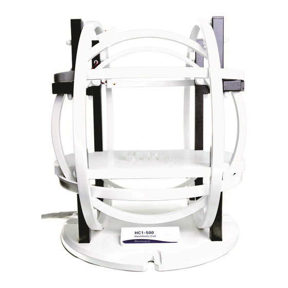
Helmholtz Coil installation manual
The following manual provide information about the use of Bartington Helmholtz Coil system and
considerations on positioning and orientation of the coil in order to ensure optimum performances are
obtained from the system. The document refers to additional documents such as the operation manuals
for separate system elements.
1.
Positioning of the coil
The Bartington Helmholtz coil systems provide users with the ability to generate stable magnetic fields.
Due to the nature of the instrument however, the field generated are leaked out of the coil, and in reverse,
external fields have the ability to distort and affect the field inside the set of coils. Because these systems
are used to generate magnetic field of amplitude similar to or within about an order of magnitude of the
Earth's magnetic field, they will be very sensitive to external environmental factors.
The first consideration should therefore be about finding a suitable location for the Helmholtz coil.
Ideally the site should be:
•
A site where permanent field distortion or gradient within the coil are negligible
•
A site where transient field distortions are avoided.
Whilst each installation and each site will be unique, there are some general recommendations which
can be given here.
To prevent permanent gradients across the coils, the system should be installed in an area clear from
permanent/fixed ferromagnetic structures such as support beams, reinforced concrete, or steel shelving
as these will distort the local magnetic field. If a coil is located too close to these elements, they will cause
distortions of both the Earth's field as well as any field generated by the coil, thus affecting the
homogeneous volume within the coil and creating gradients across the coil, reducing the performance of
the system. A non-exhaustive list of structures and elements to keep in mind is given here: metal beam
structures, metal partitions and wall covering, fences, reinforcement bars within concrete, DC current
carrying wires, metal shelving and furnitures, machinery, parked vehicles.
It is equally important to remove transient interferences caused, for example, by personnel moving
with equipment which can cause field distortions (this can range from tools with magnetic tips, to phone
or steel framed trolleys etc...), or objects having a consequential mass of ferromagnetic material moving
further away (vehicles, lifts etc...). The movement of these objects will cause low frequency field
variations, but can also, if passing close to the coils, generate slowly varying gradients across the coils.
Another consideration especially if running the coil at AC is the effect eddy currents may have. The
presence of electrically conductive material in the vicinity of the coil can see itself affected by the field
generated by the coils. In turn, eddy-currents may circulate within the material and lead to the generation
HELMHOLTZ COIL INSTALLATION AND CALIBRATION
Advertisement

Summary of Contents for Bartington Helmholtz Coil
- Page 1 Positioning of the coil The Bartington Helmholtz coil systems provide users with the ability to generate stable magnetic fields. Due to the nature of the instrument however, the field generated are leaked out of the coil, and in reverse, external fields have the ability to distort and affect the field inside the set of coils.
- Page 2 System components A complete Helmholtz coil system will include the coils, the PA1 Power Amplifier, CU1 Control Unit (which is used to interface the PA1 with an ADC card/PC), the CU2 Closed-loop module (optional but recommended if operating mainly at DC and low frequency below mains power frequencies), a National Instruments ADC card and a PC (running the operating software enabling field generation).
- Page 3 HELMHOLTZ COIL INSTALLATION AND CALIBRATION Precautions of use Some precautions are required when using the equipment. Certain elements of the system are heavy and should not be handled by one person alone. Coils and PA1 should always be carried by multiple people.
- Page 4 If using the CU2, the CU2 reference magnetometer should be placed within the coils and aligned to the coil’s axes. When mounted in a Bartington coils, the CU2 Reference Magnetometer mounting face (the one engraved) will be down, with the potting facing upwards.
- Page 5 These are the DC offsets associated with the local Earth’s field and any material surrounding the system. Place the Mag-13MS in the centre of the coil, using the provided mounting jig. Opening the Bartington Helmholtz Coil Control Software, set the coil to the correct type. Generator tab settings should be set to: o Set the field generation to 0 and DC.
- Page 6 HELMHOLTZ COIL INSTALLATION AND CALIBRATION Figure 2: Generator Tab - Offsets In the read tab, the settings should be set to: o Set the readings as DC. o Select the appropriate data to be read (AUX X Y and Z if the sensor is connected to the Auxiliary input, or DUT X Y and Z if connected to the Device Under Test port).
- Page 7 HELMHOLTZ COIL INSTALLATION AND CALIBRATION Figure 3: Read Tab - Offsets Once you have achieved the lowest possible reading, lock the locking nut (ensuring that you keep the potentiometer in place). Note that you may need to progressively tighten the locking nut, and fine tune the offset as you do so.
- Page 8 HELMHOLTZ COIL INSTALLATION AND CALIBRATION Figure 4: Generator Tab - Scaling In the read tab, the settings should be as follow: o Set the reading to RMS or PK-PK whichever is more convenient. For a pk-pk setting, you should read twice the applied field in the generator tab (or whichever value is adjusted to take into account the sensor’s scaling error).
- Page 9 Test Equipment = "HC2" (this may change to HC1, HC9, HC16 depending on the coil used) System Path = "/C/Bartington/HC2.tef" (the file name should be that of the coil used – see above) Device Path = "/C/Bartington/Mag03_100.tdf" (this file may have a different number based on its range –...
- Page 10 HELMHOLTZ COIL INSTALLATION AND CALIBRATION [Serial] (End) Note that the Test Equipment entry should correspond to the type of coil used. The *.tef file in the System path should be the same file name as the .tef file which will be described shortly.
- Page 11 HELMHOLTZ COIL INSTALLATION AND CALIBRATION Z pK-pK input Scale = 1.000000E+0 X DUT gain increace factor = 1.000000E+2 Y DUT gain increace factor = 1.000000E+2 Z DUT gain increace factor = 1.000000E+2 Noise Input Gain = 1.000000E+3 DUT gain increace Label = 1.000000E+2 DUT PSU Scale Factor = 5.000000E-1...
- Page 12 1000uT full range 100E-6 1000E-6 Once the files have been created and are stored at C:\Bartington, the test software can be installed. The only section of the software which is used for the orthogonality calibration is accessed by selecting alignment.
- Page 13 HELMHOLTZ COIL INSTALLATION AND CALIBRATION Figure 6: Factory Test Software The calibration procedure requires measurements to be taken in two opposite directions for each coil axis. Each axis is tested independently from the others. When applying a field to X, the sensor will be rotated about its X axis.
- Page 14 HELMHOLTZ COIL INSTALLATION AND CALIBRATION Figure 7: Position 0 - XYZ Sensor Match XYZ Coil With the sensor in position 0, select the X axis and record the two values given in the alignment section of the software. These will be angular errors for Y and Z and will be called Yx and Zx (Y error due...
- Page 15 HELMHOLTZ COIL INSTALLATION AND CALIBRATION Figure 8: Y and Z errors due to X Next rotate the sensor along its X axis so that is in position 1.
- Page 16 HELMHOLTZ COIL INSTALLATION AND CALIBRATION Figure 9: Position 1 - X Axis Rotation Record the new values Yx’ and Zx’. Calculate Yx and Zx target as (Yx’-Yx)/2 and (Zx’-Zx)/2. With these values calculated, using the Y->X and Z->X potentiometers, adjust the potentiometers to the target value.
- Page 17 HELMHOLTZ COIL INSTALLATION AND CALIBRATION Ensure the sensor is in Position 0 (see Figure 7). Select the Y axis and record the X and Z errors due to Y (Xy, Zy). Rotate the sensor along the Y axis to end up in position 2 (see Figure 12).
- Page 18 HELMHOLTZ COIL INSTALLATION AND CALIBRATION Figure 13: X and Z errors due to Y adjustment potentiometers o Z axis. Ensure the sensor is in Position 0 (see Figure 7). Select the Z axis and record the X and Y errors due to Z (Xz, Yz).
- Page 19 HELMHOLTZ COIL INSTALLATION AND CALIBRATION Once the orthogonality is completed, both the scaling and dc offset should be checked again and adjusted if required. Figure 15: X and Y errors due to Z adjustment potentiometers Running the coils Once the calibration of the system has been checked and is running satisfactorily, the coils can then be used.
Need help?
Do you have a question about the Helmholtz Coil and is the answer not in the manual?
Questions and answers