Advertisement
- Wiring Brochure
Mixing Expansion Module 440
1
2
Information
Application
Brochure
Brochure
Choose controls
Design your
to match
mechanical
application
applications
Overview
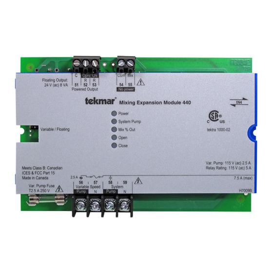
The following wiring brochure describes how to wire the tekmar Mixing Expansion Module 440. The 440 is to be installed
in an enclosure together with a tekmar Zone Manager. The 440 controls one mixing device (either variable speed injection
or floating action) and one system pump. The wiring of tekmarNet
C
Opn
Floating Output:
24 V (ac) 8 VA
51
52
Powered Output
Variable / Floating
Meets Class B: Canadian
ICES & FCC Part 15
Made in Canada
2.5 A
56
Var. Pump Fuse
Variable Speed
T2.5 A 250 V
Pump
3
Rough-in
Wiring
Rough-in
wiring
instructions
Cls
Com Mix
R
R
53
54
55
No power
Mixing Expansion Module 440
Power
System Pump
Mix % Out
Open
Close
57
58
59
System
N
Pump
N
4
5
Wiring
Brochure
Wiring and
Control settings
installation of
and sequence of
specific control
®
4 (tN4) components is simple and cost effective.
tN4
tektra 1000-02
Var. Pump: 115 V (ac) 2.5 A
Relay Rating: 115 V (ac) 5 A
tekmar wiring Enclosure (not included)
7.5 A (max)
H7009B
1 of 8
W 440
6
Data
Job
Brochure
Record
Record settings &
wiring details for
operation
future reference
tekmar Zone Manager
© 2008
W 440 - 12/08
12/08
Advertisement
Table of Contents

Summary of Contents for Tekmar Mixing Expansion Module 440
- Page 1 Overview The following wiring brochure describes how to wire the tekmar Mixing Expansion Module 440. The 440 is to be installed in an enclosure together with a tekmar Zone Manager. The 440 controls one mixing device (either variable speed injection or floating action) and one system pump.
-
Page 2: Table Of Contents
Table of Contents Wiring Symbols & Definitions ........2 Troubleshooting the Wiring ..........7 Module Installation ............3 Testing the Control ............7 Electrical Drawings ............3-5 Technical Data ..............8 Wiring the Control ............6 Wiring Symbols Demand, signals control to operate. Requires a power and neutral connection. Use 24 Fuse, field replaceable. -
Page 3: Module Installation
Module Installation Install the Mixing Expansion Module 440 in the left side of a tekmarNet ® 4 (tN4) wiring enclosure. The enclosure comes with a Zone Manager pre-installed in the right side. Review the figure below to understand the installation of the 440: To Install the 440 1. - Page 4 Electrical Application 440 E1 Description: tekmarNet 4 Mixing Expansion Module 440; Variable Speed Mixing. ® Mix Supply Sensor 24 V (ac) R & C tN4 = Mix 1 temp. Com Mix Floating Output: 24 V (ac) 8 VA Powered Output...
- Page 5 Electrical Application 440 E2 Description: tekmarNet 4 Mixing Expansion Module 440; 24 V (ac) Floating Action. ® Mixing Valve Mix Supply Floating Action Sensor 24 V (ac) Motor Com Opn Cls 24 V (ac) R & C tN4 = Mix 1 temp.
-
Page 6: Wiring The Control
The following section explains how to wire individual terminals. devices to the Mixing Expansion Module 440. For step • • Refer to the current and voltage ratings at the back by step wiring refer to the terminal number on the right of this brochure before connecting devices to this of the page. -
Page 7: Troubleshooting The Wiring
Cls (Close) terminals (51-53). The reading should be 24 V (ac) + / – 10%. 0 V (ac). Testing tekmar Sensors Terminals 54-55 To test the sensors, the actual temperature at each sensor sensor alongside the one to be tested and compare the readings. -
Page 8: Technical Data
Technical Data Mixing Expansion Module 440; Variable Speed / Floating Action Control Microprocessor PID control; This is not a safety (limit) control Packaged weight 1.16 lb. (526 g) Dimensions 3-5/8” H x 5-3/8” W x 9/16” D (92 x 137 x 14 mm)
Need help?
Do you have a question about the Mixing Expansion Module 440 and is the answer not in the manual?
Questions and answers