Advertisement
Quick Links
The smart switch box is a Z-Wave
TM
enabled wireless device fully compatible with
GPS-2000 Gerber Prime Switch
any Z-Wave
TM
enabled networks. This device is a security enabled Z-Wave Plus
product that uses encrypted Z-Wave Plus messages to communicate to other
security enabled Z-Wave Plus products. Z-Wave
TM
enabled devices displaying the Z-
Wave
TM
logo can also be used with this device regardless of the manufacturer, and
this device can also be used in other manufacturer's Z-Wave
TM
enabled networks.
This device must be used in conjunction with a Security Enabled Z-Wave Controller
in order to fully utilize all functions. Inclusion of this unit on other manufacturer's
Wireless Controller menu allows remote operation of the unit and connected load.
modules
Remote control of Dimmer/Relay
are possible with other manufacturer's
wireless Controller as well. GPS-2000 is designed to act as a repeater. Repeaters
will re-transmit the RF signal to ensure that the signal is received by its intended
destination by routing the signal around obstacles and radio dead spots. Its
functionality and supported command classes are identical when included as a
secure and non-secure device.
Adding to Z-Wave
TM
Network
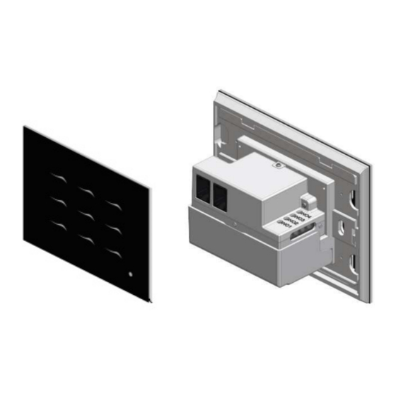
In the front case, there are nine touch screen buttons with LED light indicators which
are used to turn switches on and off, or carry out inclusion, exclusion, and reset.
The table below provides an operation summary of basic Z-Wave functions. Please
refer to the instructions of your Z-Wave
TM
Certificated Primary Controller to access
Figure 1
the Set-up function, and to Add/Remove/Associate Devices
1
Advertisement

Summary of Contents for Gerber Technology GPS-2000
- Page 1 Remote control of Dimmer/Relay are possible with other manufacturer’s wireless Controller as well. GPS-2000 is designed to act as a repeater. Repeaters will re-transmit the RF signal to ensure that the signal is received by its intended destination by routing the signal around obstacles and radio dead spots. Its functionality and supported command classes are identical when included as a secure and non-secure device.
- Page 2 the event that the primary Function Description Annotation four times and hold the button on controller looses connection. the 4th time for about 3~10 1.Set your Z-Wave controller into The green LED ⑤ will light on seconds, then release button. inclusion mode by following the when every pressing and light off when every releasing.
- Page 3 1 or 2 turns off. ③ ⑨ Dimmer The LED will change color from blue to green when the GPS-2000 Association 1. The is an always listening module corresponding dimmer module 3 or 4 turns on. Conversely, it will change...
- Page 4 On : [Command Class COMMAND CLASS MULTI CHANNEL, MULTI CHANNEL CMD ENCAP, 1. Connect GPS-2000 into a plug near the relay/dimmer to be controlled. Source endpoint = 0x00, 2. Connect the load to the PNA26 module. Make sure the load to be controlled Destination endpoint = 0x06, (or 0x01) doesn’t exceed 10A...
- Page 5 2. Controlling dimmer module by Z-Wave command Off : [Command Class COMMAND CLASS MULTI CHANNEL, MULTI CHANNEL The dimmer will respond to BASIC_SET and MULTILEVEL_SWITCH_SET CMD ENCAP, commands that are encapsulated by Multi Channel Command Encapsulation Source endpoint = 0x00, command.
- Page 6 CMD ENCAP, MULTI CHANNEL CMD ENCAP, Source endpoint = 0x00, Source endpoint = 0x08, (or 0x03) Destination endpoint = 0x03, (or 0x08) Destination endpoint = 0x00, Command Class = COMMAND_CLASS_SWITCH_MULTILEVEL, Command Class = COMMAND_CLASS_BASIC, Command = SWITCH_MULTILEVEL_SET, Command = BASIC_REPORT, Value = 0x01 ~ 0x63] Value = 0x00 ~ 0x63] Off : [Command Class COMMAND CLASS MULTI CHANNEL, MULTI CHANNEL...
- Page 7 Group2 and Group7 which correspond to relay modules 1 and 2 support Command = SWITCH_BINARY_SET, COMMAND_CLASS_SWITCH_BINARY. The relay modules 1 and 2 correspond to Value = 0xFF] endpoints 1 and 6. The device type of endpoints 1 and 6 is POWER SWITCH Off : [Command Class = COMMAND_CLASS_SWITCH_BINARY, BINARY.
- Page 8 Basic_Set from Endpoint 2 Endpoint 5 Endpoint 6 Endpoint 7 Endpoint 8 Group4 : Switch_Multilev Group1 : Group1 : Group1 : Group1 : el_Set from Lifeline Lifeline Lifeline Lifeline Endpoint 3 Group2 : Group2 : Group2 : Group2 : Group5 : Basic_Set Switch_Binary_ Basic_Set...
- Page 9 COMMAND_CLASS_SECURITY_2, COMMAND_CLASS_ASSOCIATION, COMMAND_CLASS_MULTI_CHANNEL, COMMAND_CLASS_ASSOCIATION_GRP_INFO, COMMAND_CLASS_CENTRAL_SCENE, COMMAND_CLASS_MULTI_CHANNEL_ASSOCIATION, COMMAND_CLASS_SUPERVISION, COMMAND_CLASS_SUPERVISION, COMMAND_CLASS_FIRMWARE_UPDATE_MD COMMAND_CLASS_SECURITY, Controlled Command Classes : None COMMAND_CLASS_SECURITY_2 Description : When Reset function is triggered, it will send DEVICE_RESET Controlled Command Classes : COMMAND_CLASS_BASIC ②, _LOCALLY_NOTIFICATION to nodes of group 1. Description : When one short press on smart button it will turn on the nodes of group 3 by sending Basic_Set command and send Central_Scene_Notification to Endpoint 1 :...
- Page 10 COMMAND_CLASS_SECURITY, COMMAND_CLASS_SECURITY_2 Endpoint 4 : Controlled Command Classes : COMMAND_CLASS_BASIC Device type : BASIC WALL CONTROLLER ⑥, Description : When one short press on smart button it will turn on the nodes of Supported Command Classes : COMMAND_CLASS_ZWAVEPLUS_INFO, group 6 by sending Basic_Set command and send Central_Scene_Notification to COMMAND_CLASS_CENTRAL_SCENE, ⑥, group 1 nodes.
- Page 11 COMMAND_CLASS_ASSOCIATION, COMMAND_CLASS_ASSOCIATION_GRP_INFO, COMMAND_CLASS_MULTI_CHANNEL_ASSOCIATION, 1. Auto report to Grouping 1 (Maximum 2 Nodes) COMMAND_CLASS_SUPERVISION, 1-1 Reset Event Report to Lifeline COMMAND_CLASS_SECURITY, ⑤ When user executes the reset function by pressing button , it will send a COMMAND_CLASS_SECURITY_2 “DEVICE RESET LOCALLY NOTIFICATION” to the nodes of Group1. Controlled Command Classes : COMMAND_CLASS_BASIC For example : ⑧,...
- Page 12 3. Pressing button control the correspondent Group (Maximum 2 Nodes) Source endpoint = 0x01, (or 0x06) 3-1 Pressing button to switch On/Off Relay Destination endpoint = 0x01, ① ⑦ Button correspond to relay1 and button correspond to relay2. When the relay Command Class = COMMAND_CLASS_SWITCH_BINARY, is off, shortly pressing the assigned button will turn it on and send Basic_Set Command = SWITCH_BINARY_SET,...
- Page 13 pressing the same button again will turn it back to the last level (30%) and send Value = 0x00 ~ 0x63] Switch_Multilevel_Set to the nodes of group 4 or 9. To adjust the dim level, press and hold the assigned button until the desired dim level is achieved, then release. 3-3 Pressing smart button to control the corresponding grouping nodes It will send the Switch_Multilevel_Set command to the nodes of group 4 or 9.
-
Page 14: Troubleshooting
Firmware update over the air (OTA) Switch Multilevel Highest granted Security Class GPS-2000 is based on 500 series SoC and supports Firmware Update Command Supervision None Class, it can receive the updated firmware image sent by controller via the Z-wave RF media. -
Page 15: Specification
Operating Temperature 0°C ~ 40°C Frequency Range 868.4MHz & 869.85MHz/ EU ( GPS-2000 Company of License Holder:Gerber Technology 2016 LTD 908.4MHz & 916.0MHz/ US ( GPS-2000 Address of License Holder:75 Haerez St., Kfar Hanagid, Israel, 7687500 GPS-2000 922~927MHz/ Taiwan/ Japan (... - Page 16 FCC Interference Statement transmitter. This equipment has been tested to comply with the limits for a Class B digital device, pursuant to Part 15 of the FCC Rules. These limits are designed to provide reasonable protection against harmful interference in a residential installation.
Need help?
Do you have a question about the GPS-2000 and is the answer not in the manual?
Questions and answers