Table of Contents
Advertisement
Quick Links
Advertisement
Table of Contents

Summary of Contents for Groschopp IG Series
- Page 1 © 2016 Groschopp AG ...
- Page 2 Revision index: Document type: Revision: Date: BA_IG series Rev.A 2016‐07‐22 ...
-
Page 3: Table Of Contents
Table of contents General .......................... 5 1.1 Subject of these operating instructions ................... 5 1.2 Information on these operating instructions ................... 5 1.3 Further information sources ...................... 5 1.4 Instructions on use ........................... 6 1.5 Copyright ............................ 6 1.6 Manufacturer specifications ...................... 7 1.7 Declaration of Conformity/Declaration of Incorporation ... - Page 4 Table of contents 4.2 Overall view ........................... 2 1 4.3 Safety appliances ........................... 2 2 4.4 Accessories ............................. 2 2 Transport, packaging and storage .................. 24 5.1 Safety instructions for transport .................... 2 4 5.2 Transport inspection ........................ 2 4 5.3 Handling during transport ...................... 2 5 5.4 Storage ............................ 2 5 5.5 ...
-
Page 5: General
General General Subject of these operating instructions The 2/4‐pole versions of the three‐phase motors in the IG series are described in these operating instructions. Each type designation of the motors described here is listed and explained in the "Technical data" section (see Technical data/Note). Information on these operating instructions These operating instructions enable safe and efficient handling of the motor. They are integral part of the motor and must be available to staff always. Staff must read the operating instructions of the motor thoroughly and understand them before commencing any work. Compliance with all safety instructions and guidelines stated in the operating instructions constitute the basic requirement for safe working practices. Furthermore, local accident prevention regulations and general safety directives apply to the scope of application of the motor. Illustrations in these operating instructions are only intended to convey the basic understanding and can deviate from the actual motor. In addition, pay attention to the motor documents in the appendix. NOTE These operating instructions also apply to the motors in the predecessor series with the type designation DM, ODM, WKM and ZM. Further information sources For further information and solutions from Groschopp AG (see: Manufacturer specifications, contact us or visit the homepage www.groschopp.de. P.5 IG series ... -
Page 6: Instructions On Use
Instructions on use Instructions and reactions Actions to be taken by operating staff are illustrated consecutively. The order of the actions must be adhered to. The result of the respective action is marked by an arrow. Example: Action 1 Result of action 1 Lists Lists without compulsory order are shown with an initial bullet point. Example: Item 1 Item 2 Lists with compulsory order are shown with initial numbering. Example: 1. First 2. Second Referrals Referrals to sections or text passages, in which procedures, instructions or further information are described, are depicted by blue text. Example: (see: Instructions on use) Copyright These operating instructions and all other documentation supplied are protected by copyright law. © 2016 Groschopp AG Sharing or copying documents, even as excerpts, utilization and communication of its content are not permitted unless explicitly allowed. Infringements are punishable and damage compensation is mandatory. We reserve all rights of exercising industrial protective rights. IG series P.6 ... -
Page 7: Manufacturer Specifications
General Manufacturer specifications GROSCHOPP AG Greefsallee 49 41747 Viersen Germany Phone: +49 (0)2162/374‐0 Fax: +49 (0)2162/108‐0 e‐mail: info@groschopp.de www.groschopp.de Service information: The following data is required for optimum service handling: Motor identification umber Type and extent of a fault Time and circumstances of a fault Suspected cause Declaration of Conformity/Declaration of Incorporation The product is provided with the CE mark in accordance with "European Guidelines". The Declaration of Conformity is deposited at the manufacturer (distribution company): Groschopp AG Greefsallee 49 41747 Viersen Germany Guarantee terms The guarantee conditions are included in the general terms and conditions of the manufacturer. P.7 IG series ... -
Page 8: Limitation Of Liability
General Limitation of liability All specifications and instructions contained in these operating instructions were compiled with respect to current standards and regulations and reflect the current state of technology as well as our longstanding knowledge and experience. The manufacturer assumes no liability for damages resulting from: Failure to observe the operating instructions Use other for the intended purpose Deployment of untrained or insufficiently‐trained staff, Unauthorised modifications Faulty connection, Technical modifications Failure to perform mandatory servicing, Use of non‐approved spare parts The responsibilities as agreed in the delivery contract, the general terms and conditions, the delivery conditions specified by the manufacturer as well as the applicable statutory regulations apply. We reserve the right to make technical modifications resulting from improvements and further development. IG series P.8 ... -
Page 9: Explanation Of Symbols
General 1.10 Explanation of symbols Pictograms The warnings used in these operating instructions are also indicated by a pictogram, which is intended to make a possible hazard clear. The following pictograms are used: Symbol Meaning General warning Danger from electricity Danger from hot surfaces Danger of environmental pollution General instructions and useful suggestions on handling. P.9 IG series ... -
Page 10: Warnings
General 1.11 Warnings The warnings used in these operating instructions are indicated by signal words such as DANGER, WARNING, CAUTION and ATTENTION and are intended to express the extent of the hazard. A warning symbol also refers to the type of hazard. The following warning instructions are used throughout these operating instructions: Danger to life DANGER Danger to life! Consequences of failure to observe ... Instructions for avoiding A warning of this category indicates an impending dangerous situation. If the dangerous situation is not avoided, it may lead to serious or irreversible injury or even death. Follow the instructions in this warning to avoid possible danger of serious injury or even death. Risk of injury WARNING Risk of injury! Consequences of failure to observe ... Instructions for avoiding A warning of this category indicates a potentially dangerous situation. If the dangerous situation is not avoided, it may lead to serious injury or even death. Follow the instructions in this warning to avoid possible danger of serious injury or even death. Injury to persons ... - Page 11 General Material damage ATTENTION Damage to property by... Consequences of failure to observe ... Instructions for avoiding A warning of this category indicates potential danger to property. If the situation is not avoided, it may lead to damage to property. Follow the instructions in this warning to avoid damage to property. Tips and recommendations NOTE Descriptive text… A descriptive text contains additional information that is important for further processing or for simplifying the procedure step explained. P.11 IG series ...
-
Page 12: Safety
Safety General This section provides important instructions on all safety aspects for optimum protection of staff as well as safe and smooth operation. Failure to observe the safety and handling instructions listed in these operating instructions can lead to considerable danger. Always pay attention to all warnings and instructions specified. Intended use The motor serves only as drive element for machines (according to Machine Directive 2006/42/EC) and may only be put into operation as an integrated part of the machine. The technical limits of the motor must be complied with. For this purpose, pay attention to the type plate on the motor and the technical data in the appendix of these operating instructions (see Appendix). Any use other than previously stated is considered as improper use. Foreseeable misuse Any use other than and/or going beyond the intended use of the motor can lead to dangerous situations. Only use the motor for its intended purpose. All information contained in these operating instructions must be strictly complied with. Do not make any modifications to the motor. The operator is liable for all damage caused from use for other than the intended purpose. Product monitoring Groschopp AG continues to monitor its motors after delivery. Therefore, please inform us on: any accidents; problems that occur during use of the motor; malfunctions that occur during specific operating situations; experience that could be important for other users. For contact data, see Manufacturer specifications. IG series P.12 ... -
Page 13: Fundamental Safety Instructions
Safety Fundamental safety instructions The motor is state‐of‐the‐art and was built according the EC low‐voltage directive and technical safety regulations. However, risks and impairment can still occur when using the motor: for life and limb of the operator or third party for life and limb of the maintenance staff for the machine itself and other material assets The basis for safety‐related handling and trouble‐free operation of the motor is knowledge of the safety and user instructions in this manual. NOTE The operating instructions are an integral part of the motor and must be available to staff always. Particular dangers/residual risks 2.6.1 Danger from electric current! Contact with live wires or components can lead to serious injury or even death! Do not use the motor if electrical lines, plugs or insulating housings are damaged. Perform checks according to the deadlines for recurring checks/inspections specified in the operating instructions. Work on electrical equipment may only be carried out by a qualified electrician or trained staff under the supervision and instruction of a qualified electrician in accordance with the rules of electrical engineering. Defects detected in electrical systems/equipment must be repaired immediately. If the condition represents an acute danger, the defective system, component etc. may not be used. Machine parts undergoing inspection, maintenance or repair work must be disconnected from the voltage as prescribed. Check that those parts are disconnected from the voltage supply and insulate live adjacent parts before grounding and short‐circuiting them! ... -
Page 14: Danger From Hot Surfaces
Safety 2.6.2 Danger from hot surfaces Hot surfaces can cause serious injuries. The surface of the motor can heat up strongly during operation (surface temperature > 100 °C). Do not touch the motor during operation. Allow the motor to cool sufficiently after operation. 2.6.3 Fire risk Fire and smoke can be caused by hot motor parts if operated improperly. The motor can heat up strongly during operation. Never cover the motor with inflammable materials. Ensure sufficient ventilation of the motor during operation. 2.6.4 Risk of shearing Depending on the version, the motor is equipped with a ventilator. Risk of cutting and shearing injuries from the ventilator. Never operate the motor without ventilator cover. Never reach or put objects into the openings of the ventilator. 2.6.5 Rotating components Rotating and/or linearly moving components can cause severe injury. Do not reach into or tamper with rotating components during operation. Do not open the covers during operation. Pay attention to run‐down times: Make sure that components are not in motion when opening the cover. ... -
Page 15: Staff Requirements
Safety Staff requirements 2.9.1 Qualification Inappropriate handling of the machine can result in considerable damage to persons or property. All activities shall only be carried out by qualified staff. The following qualifications are stated in these operating instructions for different fields of activities. Instructed persons were given instruction by the operator on his/her assigned tasks and possible dangers resulting from improper conduct. Specialist staff are considered specialists, who, due to their professional training, knowledge and experience as well as acknowledgement of relevant regulations, can judge the assigned work, and can recognise and avoid possible risks. Electrical specialist are employees who, due to their professional training, knowledge and experience as well as acknowledgement of relevant regulations, can judge the assigned work, and can recognise and avoid possible risks. The qualified electrician was trained for the specific work site to which he/she is deployed, and is familiar with the relevant standards and regulations. Only permit members of staff if it can be expected that they will carry out their assigned tasks reliably. Those staff members whose responsiveness is affected by substances such as drugs, alcohol or medication shall not be permitted. Staff to be trained, taught, instructed or involved in a general training program may only work under the constant supervision of an experienced person! NOTE When selecting staff, pay attention to age and occupational‐specific regulations at the location. 2.9.2 Unauthorised persons Unauthorised persons who do not fulfil the requirements are not familiar with the dangers at the work location. ... -
Page 16: Personal Protective Equipment
Safety 2.10 Personal protective equipment To minimise health risks during work, it is necessary to wear personal protective equipment. The protective equipment corresponding to the work being carried out must be worn always. Worn out or defective protective equipment must be replaced immediately. Pay attention to all notices within the work area on personal protective equipment. Always wear the following protective equipment during work: Close‐fitting protective clothing with a low tear strength Gloves for protection against injuries Protective footwear with steel caps, puncture‐resistant and oil‐resistant soles Goggles to protect the eyes from flying parts and liquids Special protective equipment is necessary when performing special work. This is dealt with in detail in individual sections. Also wear the following protective equipment during special work: Helmet for protecting your head against falling objects Ear protection in areas with high noise emission > 80 dB(A) IG series P.16 ... -
Page 17: Safety Appliances
Safety 2.11 Safety appliances When installing, the motor must be integrated into the overall safety concept of the machine. 2.12 Signs on the motor Over time, stickers and signs can become illegible due to dirt or other causes. All safety, warning and operating instructions must be maintained in legible condition. Damaged signs or stickers must be replaced immediately. The following symbols and signs are on the motor. These apply to the area immediately surrounding where they are attached. Grounding A ground connection is located at the indicated place. 2.13 Modification prohibited Any modifications, additional extensions and changes to the motor, in particular, the removal or manipulation of the safety devices is forbidden. No liability or warranty can be assumed by the manufacturer in the event of unauthorised modifications to the motor. This also applies to welding work. The electromagnetic behaviour of the motor can be impaired by extensions or modifications of any type. For this reason, do not modify or make changes to the motor without written permission from the manufacturer. 2.14 Spare parts Incorrect or defective replacement parts can lead to injury, damage, malfunction or total breakdown. Use original parts only. NOTE For further information and ordering replacement parts, contact Groschopp AG (see: Manufacturer specifications). P.17 IG series ... -
Page 18: Measures For Preventing Accidents
Safety 2.15 Measures for preventing accidents Preventive measures Always be prepared for accidents or fire. Store first aid equipment (first aid kit, covers, etc.) and fire extinguishers so that they are easily accessible. Familiarise staff with accident reporting, first aid and rescue equipment. Keep access routes free for emergency vehicles. Measures to be taken in case of accident Trigger the Emergency‐Stop system immediately. Initiate first aid measures. Remove persons from the danger area. Inform person responsible. Alert the emergency services. Keep access routes free for emergency vehicles. 2.16 Environmental protection Severe damage to the environment can result from improper handling and in particular, improper disposal of environmentally hazardous materials. Pay attention to the instructions on disposal below. When the environment is inadvertently exposed to environmentally hazardous materials, immediate measures must be taken. In case of doubt, the local authorities responsible should be notified about ... -
Page 19: Technical Data
I: Induction motor NOTE In addition to the standard versions stated above, Groschopp AG also manufactures different motor types as well as an extensive portfolio of add‐on parts. This includes: Induction motors as alternative version Add‐on components such as: frequency inverters, encoder systems and speedometers For details on the product range, please visit the homepage www.groschopp.de. P.19 IG series... -
Page 20: Type Plate
Technical data Type plate The type plate with CE mark is on the motor housing. (The illustration could be different from the actual location of the type plate) Pos. Meaning 1 Manufacturer specifications 2 Winding card number 3 Degree of protection (IP) 4 Frequency 5 Speed (in rpm) 6 Phase shift angle 7 Various technical information on the motor. In the example: Phase insulation Heat monitor Insulation class 8 Power output (in W) 9 Current consumption, respectively for star and delta circuits (in A) 10 Operating voltage, respectively for star and delta circuits (in V) at 60 Hz 11 ... -
Page 21: Setup And Function
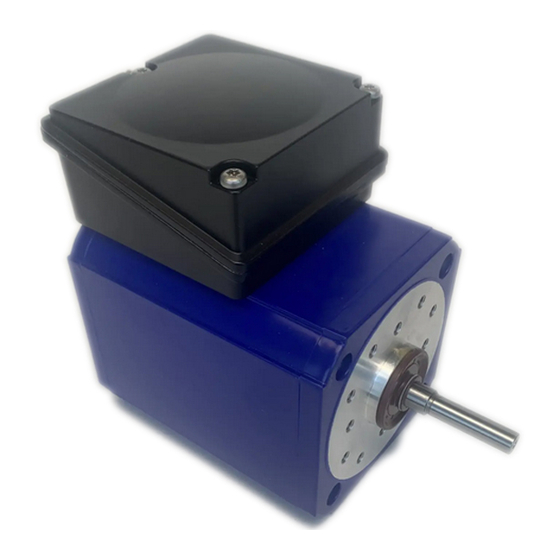
Setup and function Setup and function Description of functions The functional method of the individual motors in the IG series depends on the respective design e.g., induction motor, reluctance motor etc., (see: Appendix for more details). Overall view Normally, the three‐phase motors in the IG series consist of the following components. For details, pay attention to the product datasheet of the respective motor in the Appendix. Pos. Meaning 1 Terminal box 2 Cable insert 3 Bearing plate (for versions with ventilator: ventilator cover) 4 Mounting foot (optional) 5 Flange for connecting with a gearbox or for direct attachment 6 Output shaft 7 Housing P.21 IG series ... -
Page 22: Safety Appliances
Setup and function Safety appliances NOTE The motor may only be put into operation as an integrated part of a machine. The motor must be integrated into the overall safety concept of the machine. Accessories Gearbox (optional) NOTE When using gearboxes at the motor, other risks are possible in addition to those already mentioned in these operating instructions. Pay attention to the safety instructions in the technical documentation for the respective gearbox. NOTE If the three‐phase motor of the IG series is supplied by Groschopp AG as motor‐gearbox combination, the technical data for the corresponding gearbox is in the appendix of these operating instructions (see: Appendix). Various gearbox versions are available from Groschopp AG as optional accessories (see http://www.groschopp.de/produkte/getriebe/). IG series P.22 ... - Page 23 Setup and function Various examples of available gearbox versions are shown here. Spur gear driven type SG80 Simple worm gear type VE31‐D‐B‐2 Simple worm gear type VE31‐D‐H Simple worm gear type VE31‐G‐R (or: VE31‐G‐L) Simple worm gear type VE31‐K‐R (or: VE31‐K‐L) (version with large flange) (version with small flange) P.23 IG series ...
-
Page 24: Transport, Packaging And Storage
Transport, packaging and storage Transport, packaging and storage Safety instructions for transport Improper transport The motor and the optional gearbox can be damaged considerably in the case of improper transport. Before transporting each time, make sure that the motor and where appropriate, the drive, are packaged properly and secured against slipping. When unloading the packaging on delivery as well as during in‐house transport, proceed with care and pay attention to the symbols and instructions on the packaging. Remove the packaging only prior to installation. Transport inspection The delivery should be checked immediately for completeness and for transport damage. NOTE Failure to pay attention to the following instructions will invalidate claims to the insurer for damage. In the case of visible transport damage, proceed as follows: Receipt of delivery should only be signed under reservation (e.g. on the shipping document) with corresponding information even if damage is only suspected. If goods are delivered in containers, make sure that container and locks or seals are checked by authorised persons of the shipping company or the carrier. If containers are damaged or locks and seals have been forced open, are missing or deviate from the shipping documents, the receipt should only be signed under reservation, damage must be documented and damaged or incorrect locks stored in a safe place. Secure claims against third parties for compensation. Ask shipping carrier, other carriers, haulage companies, warehouse keepers, customs and port authorities ‐ to inspect damage jointly, ... -
Page 25: Handling During Transport
Transport, packaging and storage Handling during transport The motors and gearboxes are packaged by Groschopp AG and secured against damage. The packaged parts must be secured against slipping during transport. NOTE Use suitable safety accessories (e.g., straps) to secure the packaged parts. No attachment points are provided on the packaged parts. Use suitable aids for transporting the packaged parts. Storage Pay attention to the following for storing motors and gearboxes: Do not store outdoors. Store in a dry place. Avoid condensation always. If necessary, use long‐term corrosion protection and dehumidifiers. Store at a dust‐free location. Do not expose to aggressive media. Protect against solar radiation. Avoid mechanical vibration and damage. Storage temperature: ‐20 ‐ 40 °C When storing for longer than 3 months, check the general condition of all parts and the packaging regularly. Replenish or renew the conservation medium as necessary. NOTE The package may contain instructions for storage which exceed the specifications mentioned here. Follow these instructions accordingly. ... -
Page 26: Packaging
Transport, packaging and storage Packaging The individual packages are packed according to the expected transport conditions. Packaging should protect the individual parts from transport damage, corrosion and other damage up until installation. For this reason, do not destroy the packaging and remove it only just prior to installation. Packing material should be disposed of in accordance with the respective current legal and local regulations. ATTENTION Environmental damage due to improper disposal! Packing materials are valuable raw materials and can be used further in many ways or prepared meaningfully and can be used again. Dispose of packing materials according to environmental regulations. Pay attention to the local disposal regulations. If necessary, instruct a specialist company for disposal. IG series P.26 ... -
Page 27: Improper Assembly And Initial Startup
Work on electrical systems may only be carried out by specialist qualified electricians. Personal protective equipment Use personal protective equipment as described (see Personal protective equipment). Also pay attention to the local specifications and regulations! Improper assembly and initial startup Improper assembly and initial startup can lead to severe personal injury or material damage. Before beginning work, make sure that sufficient installation workspace is available. Be careful when handling exposed, sharp‐edged components. Pay attention to tidiness and cleanliness at the workplace! Parts and tools lying around or on top of each other can be sources of accidents. Parts must be properly installed. Adhere to specified torques for screw connections. Secure components so that they do not fall or topple. Setup/installation The motor must be fixed according to the technical specifications. Pay attention to the corresponding product datasheet and the respective drawing of the motor (see the product information supplied in Appendix). When installing the motor, pay attention to the following: Avoid structural resonance from the rotational frequency and double mains frequency. In the case of direct coupling, ensure even positioning and axial alignment of the motor. Provided sufficient ventilation for motor cooling. Make sure that exhaust air can dissipate unobstructed and that warm air is not sucked in. NOTE If solutions are required that deviate from the standard installation options, contact the Groschopp AG service department (see Manufacturer specifications). P.27 IG series ... -
Page 28: Connection Overview
Improper assembly and initial startup Connection overview The electrical connection of the motor is done via the cable inserts (2) of the terminal box (1) on the motor housing Connection to the driving machine elements (e.g., gearbox) is done via the drive shaft (3). Connection 6.4.1 Electrical connection Connect the motor according to the corresponding circuit diagram (see Appendix). For this purpose, pay attention to the following: Technical data on the type plate of the motor. Technical data of the corresponding product data sheet (see Appendix). Use assembled and shielded lines according to the technical specifications for connection. Connection: Open the terminal box with a suitable tool (screwdriver). Insert the connecting line through the screw connection of the cable insert opening in the terminal box. Tighten the screw connection so that the cable insert opening is sealed against dust and water. Make sure that the unused cable inlet is sealed against dust and water. Attach the connecting line according to the circuit diagram and check the wire connections. Check grounding/equipotential bonding of the motor housing. Close and seal the terminal box against dust and water. Make sure that there is no foreign matter, contamination or moisture in the terminal box. ... -
Page 29: Connecting The Output
Improper assembly and initial startup 6.4.2 Connecting the output The output is connected via a corresponding gearbox from Groschopp AG flanged to the motor or directly via the output shaft of the motor equipped with a feather key. Pay attention to the corresponding detail drawing in the Appendix for information on the motor‐specific dimensions and fittings. For connection of a Groschopp AG gearbox: Check the compatibility of the gearbox with the motor or contact Groschopp AG for checking. Carry out gearbox assembly and connection to the motor according the specifications from Groschopp AG. Initial startup The motor may only be put into operation as an integrated part of a machine. The machine manufacturer is solely responsible for compliance with standards and guidelines for manufacturing and operating the machine The machine is operated via a controller. For this purpose, pay attention to the overall documentation of the distributing company of the machine. 6.5.1 Checking prior to initial startup NOTE The following tests ensure safety during initial startup. Rectify any faults detected before startup. Check all electrical connections of the motor. Check the motor protection equipment. ‐ Present and functional? Check secure seating of the motor. Check the motor condition. ‐ Motor undamaged? ... -
Page 30: Test Run
Remove the feather key of the drive shaft of the motor or secure against loosening. Fr this purpose, check the following items for the motor: Direction of rotation of the motor correct? Conspicuous vibration? Conspicuous noise generation? Strong temperature rise at the motor? (The surface temperature can rise over 100 °C during normal operation) If one or more of the listed points occur: Stop operation of the motor. Allow the motor to cool down. CAUTION Risk of burns The temperature on surface of the motor can rise above 100 °C. Risk of burns if the motor is touched. Before any work on the motor: Allow the motor to cool down and check the surface temperature. Check the cause of the fault (see Faults). Eliminate the fault and check the function again. If the fault occurs again, contact the Groschopp AG service department (see Manufacturer specifications). IG series P.30 ... -
Page 31: Operation
Operation Operation The motor may only be put into operation as an integrated part of a machine. The machine is operated via a controller. For this purpose, pay attention to the overall documentation of the distributing company of the machine. NOTE For machine faults in conjunction with the motor, see Faults. P.31 IG series ... -
Page 32: Faults
Faults Faults The faults listed here refer directly to the motor. Pay attention to the overall documentation for faults that are caused by the machine. NOTE Do not take the measures listed for troubleshooting, contact the Groschopp AG service department. See Manufacturer specifications. Safety instructions Before troubleshooting: Pay attention to the overall documentation for the machine, in which the motor is installed, and pay particular attention to the safety regulations. Pay attention to run‐down and allow the motor to run down completely. Allow the motor to cool down completely. Electrical system Contact with live wires or components can lead to serious injury or even death! Switch off the electric power prior to starting work and secure it against being switched back on. Staff Troubleshooting may only be performed by trained specialist staff. Work on electrical systems may only be carried out by specialist qualified electricians. Personal protective equipment Use personal protective equipment as described (see Personal protective equipment). Also pay attention to the local specifications and regulations! Improper troubleshooting: ... -
Page 33: Fault/Troubleshooting
Improve mains network conditions. Change the star to delta circuit, Motor performance designed for pay attention to the circuit delta circuit but is connected in a diagram. star Swap phase. Wrong phase direction. Phase interchanged Motor hums and increased Brake does not vent. Check brake fault (see also Brake). current consumption Servicing by the Groschopp Coil is defective. service department required (see Runner grinds Manufacturer specifications). Check switch and supply line. Humming noise during startup A phase in the supply line is interrupted after switching on Stator winding incorrectly Check terminal board. connected Shorted coil P.33 IG series ... - Page 34 Faults Fault Cause Action Phase leak Servicing by the Groschopp service department required (see Manufacturer specifications). Fuses or motor protection Short circuit in the supply line to Eliminate short‐circuit triggers immediately. the motor Connect the supply line Supply line not correctly according to the electrical system connected documentation. Servicing by the Groschopp Short circuit in the motor. service department required (see Ground fault on the motor. Manufacturer specifications). Strong rotation speed decrease Motor overloaded Check project planning and if necessary, use a larger motor or during loading. reduce the load. ...
-
Page 35: Mechanical
Faults 8.2.2 Mechanical Fault Cause Action Check mechanics. Motor does not rotate Drive is blocked mechanically Check design. Brake does not grip Required holding torque too high Servicing by the Groschopp Brake defective service department required (see Manufacturer specifications). Grinding noise during operation Grind rotating parts Servicing by the Groschopp service department required (see Ball bearing defective Manufacturer specifications). Strong heating Ball bearing defective Servicing by the Groschopp service department required (see Manufacturer specifications). Air supply restricted Check airways. Strong oscillation Imbalanced runner ... -
Page 36: Brake
Faults 8.2.3 Brake Fault Cause Action Connect the brake according to Brake does not vent. Voltage applied incorrectly the electrical system documentation. Servicing by the Groschopp Max. permissible air gap service department required (see exceeded Manufacturer specifications). Brake lining worn Connect the supply line Voltage drop along the supply line >10% according to the electrical system documentation. Establish sufficient cooling or Insufficient cooling, brake becomes too hot clean air cooling channels. Brake coil short‐circuited or Servicing by the Groschopp service department required (see ground fault ... -
Page 37: Maintenance/Cleaning
Maintenance/cleaning Maintenance/cleaning Safety instructions Before maintenance and cleaning work: Pay attention to the overall documentation for the machine, in which the motor is installed, and pay particular attention to the safety regulations. Pay attention to run‐down and allow the motor to run down completely. Allow the motor to cool down completely. Electrical system Contact with live wires or components can lead to serious injury or even death! Switch off the electric power prior to starting work and secure it against being switched back on. Staff Maintenance and cleaning work may only be performed by trained specialist staff. Work on electrical systems may only be carried out by specialist qualified electricians. Personal protective equipment Use personal protective equipment as described (see Personal protective equipment). Also pay attention to the local specifications and regulations! Improper maintenance work Improper maintenance work can lead to severe personal injury or material damage. Before beginning work, make sure that sufficient installation workspace is available. Be careful when handling exposed, sharp‐edged components. Pay attention to tidiness and cleanliness at the workplace! Parts and tools lying around or on top of each other can be sources of accidents. Parts must be properly installed. Adhere to specified torques for screw connections. Secure components so that they do not fall or topple. Cleaning ... -
Page 38: Maintenance
The three‐phase motors in the IG series are maintenance free. To increase the service life of the motor, pay attention to the following: Time period Action Every 6000 operating hours* Inspect motor and: perform visual inspection. check running noises. clean cooling air channels. check housing surfaces and repair or renew corrosion protection/paintwork if necessary. The maintenance interval depends on the operating conditions of the motor. Ware can increase with strong load and make shorter maintenance intervals necessary. 9.3.2 Replacing worn parts/components NOTE Contact Groschopp AG to replace worn parts or components. (See Manufacturer specifications) 9.3.3 Lubrication NOTE The motor bearings have lifetime lubrication. 9.3.4 Customised versions NOTE If the three‐phase motor in the IG series was ordered as a customised version, other different maintenance instructions may apply. Read the information supplied in the appendix of these operating instructions for this and/or contact Groschopp AG (see: Appendix). (See Manufacturer specifications) IG series ... -
Page 39: Decommissioning And Disposal
Decommissioning and disposal Decommissioning and disposal 10.1 Safety instructions Before decommissioning and dismantling: Pay attention to the overall documentation for the machine, in which the motor is installed, and pay particular attention to the safety regulations. Pay attention to run‐down and allow the motor to run down completely. Allow the motor to cool down completely. Electrical system Contact with live wires or components can lead to serious injury or even death! Switch off the electric power prior to starting work and secure it against being switched back on. Staff Decommissioning and dismantling the motor may only be performed by trained specialist staff. Work on electrical systems may only be carried out by specialist qualified electricians. Personal protective equipment Use personal protective equipment as described (see Personal protective equipment). Also pay attention to the local specifications and regulations! Improper decommissioning and dismantling: Improper decommissioning and dismantling can lead to severe personal injury or material damage. Before beginning work, make sure that sufficient installation workspace is available. Be careful when handling exposed, sharp‐edged components. Pay attention to tidiness and cleanliness at the workplace! Parts and tools lying around or on top of each other can be sources of accidents. Parts must be properly installed. Adhere to specified torques for screw connections. ... - Page 40 Decommissioning and disposal 10.3 Disposal Dispose of the motor according the current local regulations. ATTENTION Environmental damage resulting from incorrect disposal! Incorrect disposal can cause environmental damage. Electrical scrap, electronic components, lubricants and other accessories are subject to special waste handling and must be disposed of by authorised specialist companies only! NOTE The local authorities or special waste disposal companies can provide information on proper disposal according to environmental regulations. IG series P.40 ...
-
Page 41: Appendix
Appendix Appendix 11.1 Document list Product datasheet incl. circuit diagram .. P.41 IG series ... - Page 42 IG series P.42 ...
- Page 43 P.43 IG series ...
- Page 44 Groschopp AG Greefallee 49 41747 Viersen Germany ...
Need help?
Do you have a question about the IG Series and is the answer not in the manual?
Questions and answers