
Related Manuals for Leica BIOSYSTEMS CM3600 XP


Summary of Contents for Leica BIOSYSTEMS CM3600 XP
- Page 1 Leica CM3600 XP Cryostat Instructions for Use English Order No.: 14 0417 80101 - Revision H Always keep this manual with the instrument. Read carefully before working with the instrument. Version 6.9, Revision H - 11.2020...
- Page 3 – including any electronic systems and media – requires express prior permission in writing by Leica Biosystems Nussloch GmbH. For the instrument serial number and year of manufacture, please refer to the nameplate on the back of the instrument.
-
Page 4: Table Of Contents
Important Information ....................Symbols and their meaning ......................7 Instrument type ......................... 9 User group ..........................9 Intended use ..........................10 Characteristics of the Leica CM3600 XP ................ Layout of the Leica CM3600 XP ....................11 Technical data ..........................12 Instrument parts ........................14 Function ...........................15 Safety ........................ - Page 5 6.15 Printing labels ..........................60 6.16 Foot switch ..........................60 6.17 User log-in/log-out ........................60 6.18 Quitting the application ......................60 Operating the Leica CM3600 XP ................... Check list ..........................61 Switching the instrument on ......................61 Starting the software ........................61 Setting the chamber temperature ....................62 Specimen stages ........................62...
- Page 6 Table of contents Cleaning and Maintenance ..................Cleaning ...........................76 8.1.1 Removing the microtome ......................76 Warranty and Service ....................Decommissioning and Disposal ................... 12. Decontamination Confirmation ..................Version 6.9, Revision H...
-
Page 7: Important Information
Environmental protection symbol of the China RoHS directive. The number in the symbol indicates the "Environment-friendly Use Period" of the product. The symbol is used if a substance restricted in China is used in excess of the maximum permitted limit. Leica CM3600 XP... - Page 8 Important Information Symbol: Title of the symbol: WEEE Symbol Description: Symbol for labeling electrical and electronic equipment in accordance with Section 7 of the German Electrical and Electronic Equipment Act (ElektroG). ElektroG is the law regarding the sale, return and environmentally sound disposal of electrical and electronic equipment. Symbol: Title of the symbol: CE Compliance...
-
Page 9: Instrument Type
The exact data of the different instrument versions are specified in Chapter (→ p. 12 – 2.2 Technical data). User group Only trained laboratory personnel may operate the Leica CM3600 XP. The instrument is intended for professional use only. Prior to operating the instrument, the operator must carefully read and understand these Instructions for Use and must familiarize him/herself with all technical details of the instrument. -
Page 10: Intended Use
Important Information Intended use The Leica CM3600 XP is a PLC-controlled and motorized precision cryomacrotome for largesurface sections, equipped with a convection-cooled chamber for deep-freezing, sectioning and freeze-drying large biological and industrial specimens. The instrument is designed for the aforementioned applications only and must be operated according to the instructions in these Instructions for Use. -
Page 11: Characteristics Of The Leica Cm3600 Xp
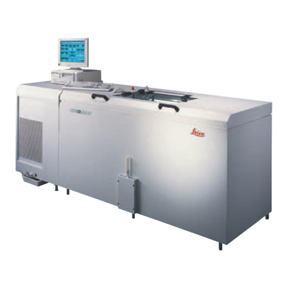
Characteristics of the Leica CM3600 XP Characteristics of the Leica CM3600 XP Layout of the Leica CM3600 XP Fig. 1 Commercially available computer with monitor, keyboard and mouse. Port and switch The port and switch panel contains the main power switch... -
Page 12: Technical Data
Knife holder for disposable blade holder: 160 mm Knife (160 mm) with facet angle of: 20°, 35° Control unit The Leica CM3600 XP is equipped with a commercially available computer with monitor, keyboard and mouse. For further information, please refer to the manual of the PC. Operating system: Windows ®... - Page 13 Characteristics of the Leica CM3600 XP • Nominal frequency: 50 Hz • Line voltage tolerance: ± 10 % • Power draw: 2400 VA • Automatic cutout: 3 x 8 A / 1 x 16 A • Power safety switch in accordance with DIN IEC 127-2 • Power plug (CEE, in accordance with IEC 60309) Mennekes ProTOP 13A (fits to socket type 3473) 208 V / 60 Hz • Nominal supply voltages: 208 V AC...
-
Page 14: Instrument Parts
The user must wear hearing protection when using the extraction. Instrument parts The Leica CM3600 XP consists of a sliding microtome in a large-volume cryochamber. The instrument is designed for cryosectioning large specimens or for processing specimens with the so-called cryo-planing technique. -
Page 15: Function
Once the desired specimen block height has been reached, those sections that will actually be used for further examination are collected manually via the knee lever. The Leica CM3600 XP is operated via PC and/or manually via the knee lever. All data entries are made via the PC. -
Page 16: Safety
Safety Safety Warning The safety and caution notes in this chapter must be observed at all times. Be sure to read these notes even if you are already familiar with the operation and use of other Leica products. Safety notes These Instructions for Use include important instructions and information related to the operating safety and maintenance of the instrument. - Page 17 • For removing the microtome (weight is approx. 190 kg) from the cryochamber, a ceiling crane capable of carrying that weight should be available. • For safety reasons, we strongly advise against lifting the microtome (approx. 190 kg) from the cryochamber without appropriate lifting gear. Do not attempt to lift the microtome from the cyrochamber manually, even if several persons are there to help. Leica CM3600 XP...
-
Page 18: Safety Features
• Prior to any work involving the knife or the microtome, or in the cryochamber, swing the knee lever upwards, see (→ p. 19 – 3.3.2 Knee lever). Safety features 3.3.1 Emergency stop switch The Leica CM3600 XP is equipped with an Emergency stop switch (→ Fig. 2-1) located on the cabinet to the left of the window. -
Page 19: Knee Lever
• Afterwards, the sectioning program has to be reselected, see (→ p. 35 – 6.4.7 Section program). 3.3.2 Knee lever Never leave the Leica CM3600 XP unattended when the knee lever (→ Fig. 3-1) is folded out to prevent the microtome from being set in motion accidentally. -
Page 20: Window
Safety 3.3.3 Window The window is heatable and equipped with a locking knob (→ Fig. 4-2). To open the window, lift locking knob (→ Fig. 4-2) slightly upwards and turn it by 180°. Warning You must make sure that the window has been locked before the chamber lid is opened. -
Page 21: Site Requirements
• Avoid vibrations, direct sunlight and extreme variations in temperature. • Installation elevation up to 2,000 m above sea level. If possible at all, the room should be air-conditioned. If ambient conditions are not maintained as specified, instrument performance may be negatively affected (lowest specified temperature may not be reached, frost may accumulate). All transport paths for the Leica CM3600 XP must be at least 1.50 m wide; especially doorways must have that width. 95 cm is a sufficient width for the instrument to pass through a doorway at an angle (if the instrument can pass straight through the doorway, a width of 95 cm will be sufficient). The Leica CM3600 XP has a total length (refrigeration and control unit plus cabinet) of 2.70 m or 2.80 m including the connecting lines on the left side of the refrigeration and control unit, i. e. a minimum installation wall width of 2.90 m is required to install the instrument. Ideally the wall should measure 3.50 m or more to provide sufficient access to the left side of the instrument for technical service work. The required minimum distance between the back panel of the instrument and the wall is 30 cm, the recommended distance is 50 cm. Leica CM3600 XP... -
Page 22: Electrical Connections
Site requirements Room requirements Installation wall, ideal dimensions (view from above) 1 LEICA CM3600 XP 2 approx. 3.5 m 3 0.5 m 4 approx. 2.7 m Fig. 6 5 approx. 0.8 m Note Room temperatures and humidity levels in excess of the recommendations above will affect the cryostat's cooling capacity and the lowest stated temperatures will not be reached. -
Page 23: Installation
Installation Installation Unpacking and installation Only duly trained personnel may unpack and install the Leica CM3600 XP. Please contact your local Leica sales organization for appropriate advice. Caution Instrument insufficiently leveled Damage to the instrument and insufficient functioning • Do not apply any changes to the machine feet at the bottom of the instrument that are used for leveling. -
Page 24: Port And Switch Panel
Installation Qty. Designation Order No. Allen key with handle, size 4.0 14 0194 04782 Allen key with handle, size 5.0 14 0194 04760 Allen key with handle, size 6.0 14 0194 03959 Double open-ended wrench, size 14/15 14 0329 38799 Double open-ended wrench, size 16/17 14 0329 38800 Pair of safety gloves, size S... -
Page 25: Port And Switch Functions
• The green LED in the switch button lights up. • To deactivate the local alarm function, press the alarm signal switch once again. • The green LED in the switch button is extinguished. Connection for external alarm (→ Fig. 7-7) Forwarding an external alarm. Leica CM3600 XP... -
Page 26: Fuses
The wiring diagram shown here illustrates how the socket for the external alarm is wired in the instrument. The specified digits correspond to those on the plug provided. Indicator LEDs (→ Fig. 7-8) Indicate function of the refrigerating sets. Automatic cutout (→ Fig. 7-9) Protects the refrigerating sets and all electronic components. 5.3.2 Fuses The Leica CM3600 XP is equipped with the following fuses: Version 6.9, Revision H... - Page 27 • Flip it upwards to switch it back on. Fig. 11 The Leica CM3600 XP is equipped with a commercially available computer with monitor, keyboard and mouse. For further information, please refer to the manual of the PC. Note If a computer is to be provided by the user, please request the required PC configuration in advance from your responsible Leica sales company.
-
Page 28: Software
Software Software Start and log-in procedure Prerequisite: PC must be switched on and the Microsoft Windows operating system must have booted ® and be ready for service. • Double-clicking the CM3600 icon starts the application. Login screen: • Type the user name (→ Fig. 12-1) in the identification field. -
Page 29: Description Of The Window Elements
Clicking on the icon opens the Parameter setting window. Clicking on the icon opens the Temperature curves window. Clicking on the icon opens the Chronological event list window. Clicking on the icon opens the Alarm list window. Leica CM3600 XP... - Page 30 Software Toolbar icons Clicking on the icon switches the cryochamber illumination on or off. The icon will light up yellow when it is active. Clicking on the icon opens the Section documentation window. Clicking on the icon activates the Photo mode.
-
Page 31: Initialization
After the initialization procedure has been completed, the color of the Init button will first change from yellow to green and after a few seconds, the caption on the button will change from Init to Automatic. The microtome is now ready to operate, see (→ p. 36 – 6.4.9 Operation mode). Leica CM3600 XP... -
Page 32: Main Window
Software Note Once initialization process has been started, it can only be interrupted by pressing the Emergency stop switch, see (→ p. 18 – 3.3.1 Emergency stop switch). Main window The main window either opens up automatically after completing the start and log-in procedure or by clicking on the Main window icon. -
Page 33: Time
• The knife movement buttons can only be used when the Manual operating mode has been set, see (→ p. 36 – 6.4.9 Operation mode). • The entry limit for the actual and target position can either be a maximum of 100,000 or 200,000 μm, depending on the knife holder position. Leica CM3600 XP... - Page 34 Software Fig. 21 16 Knife up • Clicking on this button briefly moves the knife holder upwards. • If you click on and hold this icon, the knife holder will continue to move upward until the left mouse button is released. • While active, the icon blinks yellow. 17 Knife down • Clicking on this button briefly moves the knife holder downwards.
-
Page 35: Extraction System
• Clicking on the button once more restarts the section program, resuming the current section where if was left off. Note The buttons can be activated only in Automatic mode. Clicking on the Start/Stop button located in the Mode field starts or stops the section program, see (→ p. 36 – 6.4.9 Operation mode). Leica CM3600 XP... -
Page 36: Sledge Speed
Software 6.4.8 Sledge speed Displays current sectioning or return stroke speed in mm/s (millimeters per second). • To modify any of the settings, click on the corresponding value. Fig. 24 Note The graphic display is active only while sectioning is in progress. The currently selected sectioning and return stroke speed are displayed via a green bar on a scale of 0 - 80 mm/s. 6.4.9 Operation mode Displays current sectioning or return stroke speed in mm/s (millimeters per second). -
Page 37: Cutting Window
Clicking here opens up an entry window. The value to where the microtome sledge can be manually adjusted on a scale of 0 - 500 mm for the left limit position can be set here. Right block edge button (→ Fig. 26-5) Clicking here opens up an entry window. The value to where the microtome sledge can be manually adjusted on a scale of 0 - 450 mm for the right limit position can be set here. Parameter settings Clicking on Parameter settings icon opens the parameter settings window. Leica CM3600 XP... -
Page 38: Parameter Settings
Software Fig. 27 The working area of the parameter settings window is divided as follows: Parameter settings Initialization Password list Language selection Configuration Reference voltages 6.5.1 Parameter settings Different settings can be selected using the Parameter setting menu. Fig. 28 Version 6.9, Revision H... - Page 39 Defrost time 2 dialog box (→ Fig. 31). • Click on individual parameters (hours or minutes) to change the corresponding settings. Fig. 31 • The entry must be confirmed by pressing the Ok button. Active/Inactive button (→ Fig. 28-7) Clicking on this button activates or deactivates the 2nd automatic defrost cycle. Leica CM3600 XP...
- Page 40 Software Dehydration date (→ Fig. 28-8) Dehydration start time (→ Fig. 28-9) Dehydration duration (→ Fig. 28-10) Displays start date and time, and duration of the automatic dehydration cycle. Clicking on one of the indications opens the Dehydration time dialog box (→ Fig. 32). • Click on individual parameters (day, month, year, hour or minutes) to change the corresponding settings.
-
Page 41: Password Management
Full name Displays full user name. User rights Displays the corresponding access right. The administrator has full access to all application functions. Users have only limited access. Close Clicking on this button closes the User configuration window. Leica CM3600 XP... - Page 42 Software Note • Double-clicking a line in the configuration display opens the User configuration dialog box (→ Fig. 34). • Administrators have full access to all application functions. Users do not have access to password management and to the configuration parameters in the Parameter setting window. Fig. 34 In the User configuration dialog box, the following settings can be selected: Displays the running number. No changes can be made in this field.
-
Page 43: Configuration
Text substudy (→ Fig. 35-2) tabs The structure of the two tabs is identical. A header and 7 freely selectable comments for each main study or substudy can be defined. The text entered into the 8 input fields is copied into the dialog box for creating main studies and substudies. Each individual text can consist of up to 30 characters. The configuration of a main study or substudy is covered in Chapter (→ p. 55 – 6.10 Section documentation). Leica CM3600 XP... - Page 44 Software Fig. 36 Measured values tab (→ Fig. 35-3) Selecting the measured values that are to be displayed in the Section documentation window after selecting a main study or substudy. The configuration of a main study or substudy is covered in Chapter (→ p. 55 – 6.10 Section documentation). Fig. 37 The following measured values can be selected: • Set chamber temperature target value • Chamber temperature actual value • Alarm temperature...
- Page 45 You can enter the text for the labels in this tab, see (→ p. 60 – 6.15 Printing labels). • 9 lines of 50 characters each can be entered. Lines where no characters have been entered are printed as empty lines. • Clicking on the Bold checkbox in the corresponding line activates bold print. • Specific information can be entered during label printing for the output of predefined variables commencing with the special character "@". Leica CM3600 XP...
- Page 46 Software Fig. 39 Note • Repeating the variable wild card defines the length of the variable. The variable wild card @333, for example, will display the "target cryochamber temperature" with a length of 4 characters. • The "@" character represents one character. • Text variables are always printed left-justified, numbers right-justified. • Possible variables are listed in the following list. Main study – name Substudy – comment line 5 Main study – comment line 1 Substudy – comment line 6 Main study –...
-
Page 47: Reference Voltages
6.5.4 Reference voltages Displays the current reference voltage in volts is inactive. Buttons 1 to 8 Buttons 1 to 8 are inactive. Fig. 42 6.5.5 Language selection The flag buttons indicate the languages that can be selected. Clicking on one of the flag symbols changes the user interface to the corresponding language. Fig. 43 Leica CM3600 XP... -
Page 48: Initialization
Software 6.5.6 Initialization Clicking the Execute button in the initialization field opens the Main window and the Init button reappears in the Mode field. Clicking the Init button opens the Safety check – initialisation dialog box, (→ p. 31 – 6.3 Initialization). Fig. 44 Temperature curves Clicking the Temperature curves icon opens the window. -
Page 49: Work Space
The following check boxes can be activated/deactivated via a mouse click: T1 to 1 T2 to 2 T3 tv1 T4 tv Head I T5 tv2,I T6 tv2,II T7 tHg2 T8 Box 6.6.2 Diagram Fig. 47 Leica CM3600 XP... -
Page 50: Chronological Event List
Software The window contains the following areas: Temperature in degree centigrade Graphical representation of the 8 temperature on the y-axis measuring points attached to the instrument by colored-coded lines Time and date on the x-axis The diagram can be enlarged as follows: • Within the diagram, press and hold the left mouse button. -
Page 51: Work Space
Clicking on an event in the event table activates the Comment field. You can enter a comment regarding the selected event. After confirmation with the Enter button, the note will be displayed in the event table. Number Number of events displayed in the events list. Print Clicking on this button creates a screen printout of the current display. Leica CM3600 XP... -
Page 52: Event List
Software Export file Clicking on this button exports the event table to a text file, see (→ Fig. 38-6) (→ Fig. 38-7). 6.7.2 Event list Fig. 51 The table is divided into the following columns: Date/time Date and time of the events. User Name of the user who was logged in when the event occurred. Message Event messages (short description of event). Comment Display of comments related to the events, see (→... -
Page 53: Work Space
(→ p. 35 – 6.4.7 Section program). 6.8.1 Work space Fig. 53 In the work space the following parameters can be selected: Filter Clicking this button opens the Filter dialog box, see (→ p. 51 – 6.7.1 Work space). Leica CM3600 XP... -
Page 54: Alarm List
Software Comment Clicking an event in the alarm list activates the Comment field. You can enter a comment regarding the selected event. After confirmation with the Enter button, the note will be displayed in the alarm list. Number Number of alarm messages displayed in the alarm list. Confirm By clicking on this button the currently registered user confirms the alarm message previously selected in the alarm list. Print Clicking on this button creates a screen printout of the current display. -
Page 55: Error Messages: Meaning And Troubleshooting
Click on the symbol to switch on the illumination of the cryochamber. Another mouse click will switch the chamber illumination back off. Active icons will light up in yellow. 6.10 Section documentation Click on the Section documentation symbol to open the corresponding window. Leica CM3600 XP... - Page 56 Software Fig. 55 The window contains the following areas: Tree diagram Event table Studies protocol Tree diagram Displays all main studies or substudies in a tree diagram. For navigation purposes, click on the preceding plus or minus sign. The different study types are identified by the preceding colored folder symbols: Yellow folder icon Collective folder for main studies Green folder icon...
- Page 57 A dialog box for a new main study or substudy will open up. Fig. 58 • Enter the name of the new main study or substudy. • Press the Ok button to confirm the entry and close the dialog box. When clicking on a created substudy in the tree diagram, the following display will appear in the Studies protocol area: Leica CM3600 XP...
- Page 58 Software Fig. 59 The table is divided into the following columns: Displays the running number automatically allocated by the application, in the order of date of creation of the main study Date/Time Current date/time when the section was made T-set Set temperature at the time the section was made T-actual Current temperature at the time the section was made T-error...
-
Page 59: Photo Mode
PDF format. ® 6.14 Save Clicking the Save icon saves the section data. This documents all sections. All sections added by pressing the foot switch are documented, see (→ p. 60 – 6.16 Foot switch). Leica CM3600 XP... -
Page 60: Printing Labels
Software 6.15 Printing labels Clicking the Label printing icon opens the label printing window. When activated, the icon will light up in green. When the label printing feature is activated, a label will be printed every time a section has been completed. -
Page 61: Operating The Leica Cm3600 Xp
Operating the Leica CM3600 XP Operating the Leica CM3600 XP Note To ensure proper handling of the Leica CM3600 XP as well as use of the specimen stages and the specimen blocks themselves, we strongly recommend participating in Leica application training. Check list Note • The checklist below provides an overview on how to successfully operate the Leica CM3600 XP. -
Page 62: Setting The Chamber Temperature
Operating the Leica CM3600 XP Setting the chamber temperature Proceed as follows: • Open the Parameter setting window in the software and adjust the cryochamber temperature to the target value, see (→ p. 38 – 6.5.1 Parameter settings). Specimen stages This chapter provides instructions on how to insert the specimen stages. -
Page 63: Inserting The Specimen Stage, Orientable, With Ball-Joint
Operating the Leica CM3600 XP Warning • Prior to any work involving the knife or the microtome, or inside the cryochamber, activate the Emergency stop switch, see (→ p. 18 – 3.3.1 Emergency stop switch). • Prior to any work involving the knife or the microtome, or in the cryochamber, swing the knee lever upwards, see (→... - Page 64 Operating the Leica CM3600 XP Fig. 66 Fig. 67 7.5.2 Inserting the specimen stage, non-orientable Required tools: • Allen key, size 6 Proceed as follows: • Use the knee lever to move the sledge to the right-side reversal position, see (→ p. 36 – 6.4.9 Operation mode) (→...
-
Page 65: Knife
This chapter provides instructions on how to insert the knives. • Since there is a considerable risk of injury, the safety notes listed above must be observed. • Two types of knives can be used in the Leica CM3600 XP: Leica CM3600 XP... - Page 66 Operating the Leica CM3600 XP Standard knife Disposable blade holder and blade Fig. 72 Fig. 73 7.6.1 Inserting standard knives To insert a standard knife, proceed as follows. Required tools: • Allen key, size 4 Proceed as follows: • Use the knee lever to move the sledge to the right-side reversal position, see (→...
-
Page 67: Inserting The Disposable Blade Holder With Disposable Blade
Operating the Leica CM3600 XP • Remove the screws (→ Fig. 74-1) and lift off the pressure plate (→ Fig. 74-2). • Attach the knife (→ Fig. 74-3) to the base (→ Fig. 74-4). • Attach the pressure plate (→ Fig. 74-2) to the knife (→ Fig. 74-3). • Attach the screws (→ Fig. 74-1). - Page 68 Operating the Leica CM3600 XP • Remove the screws (→ Fig. 76-1) and lift off the pressure plate (→ Fig. 76-2). • Attach the disposable blade holder (→ Fig. 76-3) onto the base (→ Fig. 76-4). • Attach the pressure plate (→ Fig. 76-2) to the disposable blade holder (→ Fig. 76-3).
-
Page 69: Adjusting The Knife Angle
Operating the Leica CM3600 XP • Tighten the screws (→ Fig. 77-9) of the disposable blade holder (→ Fig. 76-3). • Loosen the screws (→ Fig. 76-1). • Align the disposable blade holder (→ Fig. 76-3) using the positioning tool (→ Fig. 77-6). • To do so, attach the positioning tool to the knife holder from the outside (→ Fig. 77-7). - Page 70 Operating the Leica CM3600 XP Setting the trimming parameters Warning • For reasons of safety and accuracy, the maximum trimming thickness should not exceed 100 μm per section. • When trimming biological material (particularly bone), the section thickness should not exceed 50 μm. Proceed as follows: • Open the Main window in the software. • Afterwards, adjust the desired section thickness, sledge speed, cutting window and section program, (→...
-
Page 71: Dehydrating The Sections
Operating the Leica CM3600 XP Warning • Wear safety gloves. • Never try to catch or grab the knife. • Never put your hands into the space between specimen and knife. Proceed as follows: • Select manual operating mode and adjust the desired section thickness. - Page 72 Operating the Leica CM3600 XP During the course of a dehydration cycle, the automatic defrost cycles are skipped and carried out immediately after the dehydration procedure is completed. Proceed as follows: • Open the Main window in the software and adjust the automatic dehydration, see (→...
-
Page 73: Knife Holder Description
Operating the Leica CM3600 XP 7.10.2 Knife holder description (→ Fig. 81) shows the knife holder in the 100 mm position of vertical height. • A groove (→ Fig. 83-2) in the support columns (→ Fig. 83-1) mark the 100 mm position. This requires that the groove match the upper edge of the knife holder, see (→ Fig. 83). - Page 74 Operating the Leica CM3600 XP 7.10.3 Knife holder height adjustment • To adjust the knife holder on the support columns (→ Fig. 83-1), first unscrew both clamping levers (→ Fig. 82-7) on the bottom side. • Afterwards, slightly unscrew the 4 knurled screws (→ Fig. 82-6) and loosen the other two clamping levers.
-
Page 75: Sectioning Thick Blocks
Operating the Leica CM3600 XP 7.10.5 Sectioning thick blocks • Move the support columns (→ Fig. 85-1) with the knife holder (by clicking Knife Up (→ Fig. 21-16), (→Fig. 21-18)) into the uppermost position. • Position the knife holder with the upper edge at the very top on the columns for the 200 mm position (→ Fig. 85). -
Page 76: Cleaning And Maintenance
Cleaning and Maintenance Cleaning and Maintenance Cleaning Warning • Switch the instrument off before each cleaning. • Wear safety gloves when cleaning the instrument. • When using cleaning agents, observe the manufacturer's safety instructions and the laboratory regulations valid in the country of use. • Do not use any of the following for cleaning the outside surfaces of the instrument: alcohol, detergents containing alcohol (window cleaner!), abrasive cleaning powders, solvents containing acetone or xylene! - Page 77 • Fasten cables or straps that have a sufficient carrying capacity to the carrying handles (→ Fig. 87-8). • Carefully lift the microtome (→ Fig. 87-5) out of the cabinet using the crane. • In doing so, securely fasten the microtome (→ Fig. 87-5) to prevent rotation or vibrations as this could lead to damage to the cabinet. Leica CM3600 XP...
- Page 78 Cleaning and Maintenance Maintenance Note • The instrument requires maintenance from Leica Service at an interval of once per year. • The pushbutton switch of the refrigeration must likewise be pressed at least once a year. 8.2.1 Oiling Note Be sure to check the oil level every day and before each sectioning procedure. Checking the oil level Unscrew both covers (→ Fig. 88-1).
- Page 79 Automatic defrost II If the Automatic defrost cycle I is not sufficient (high humidity, high ambient temperature), defrost cycle II is to be activated in addition, see (→ p. 38 – 6.5.1 Parameter settings). Manual defrost This defrost cycle can be activated manually and starts immediately, see (→ p. 33 – 6.4.3 Automatic defrost). Leica CM3600 XP...
- Page 80 Cleaning and Maintenance Optional Accessories Ordering information Designation Order No. Specimen stages Specimen stage, non-orientable, 40 x 80 mm 14 0022 50103 Specimen stage, non-orientable, 80 x 180 mm 14 0022 50105 Specimen stage, orientable, with ball-and-socket joint 120 x 200 mm 14 0022 50106 Specimen stage, orientable, with ball-and-socket joint 120 x 250 mm 14 0417 19635 Specimen stage, orientable, 150 x 450 mm 14 0022 50107 Specimen holders Special specimen holder, orientable, with ball-and-socket joint, for 14 0417 24784 non-orientable specimen stages, maximum specimen size 55 x 70 mm Embedding frames...
- Page 81 Low-temperature grease, for Leica CM3600 XP 14 0022 50192 Dehydration accessories Dehydration frames (plastic) for Leica CM3600 XP 14 0417 32995 Frame holder (for 4 dehydration frames) for Leica CM3600 XP 14 0417 32996 Other accessories Section waste tray 14 0417 32980...
-
Page 82: Warranty And Service
Warranty and Service 10. Warranty and Service Warranty Leica Biosystems Nussloch GmbH guarantees that the contractual product delivered has been subjected to a comprehensive quality control procedure based on the Leica in-house testing standards, and that the product is faultless and complies with all technical specifications and/or agreed characteristics warranted. The scope of the warranty is based on the content of the concluded agreement. The warranty terms of your Leica sales organization or the organization from which you have purchased the contractual product shall apply exclusively. -
Page 83: Decommissioning And Disposal
Please comply with the Cleaning and Maintenance chapter and the Decontamination Declaration at the end of these Instructions for Use for notes on cleaning the Leica CM3600 XP. The instrument can be contaminated when using biohazardous specimens. Thorough disinfecting is required before re-commissioning or disposal (e. g. multiple cleaning steps, disinfection or sterilization). -
Page 84: Decontamination Confirmation
Decontamination Confirmation 12. Decontamination Confirmation Any product that is to be returned to Leica Biosystems or serviced on site must be properly cleaned and decontaminated. The associated decontamination certificate template can be found on our website www. LeicaBiosystems.com in the product menu. This template must be used to enter all required data. If a product is returned, a copy of the completed and signed decontamination certificate must either be enclosed or handed over to a service technician. The user shall be responsible for products that are returned without a completed decontamination certificate or with a missing decontamination certificate. - Page 86 Leica Biosystems Nussloch GmbH Heidelberger Strasse 17 - 19 69226 Nussloch Germany Tel.: +49 - (0) 6224 - 143 0 Fax: +49 - (0) 6224 - 143 268 Web: www.LeicaBiosystems.com...
Need help?
Do you have a question about the CM3600 XP and is the answer not in the manual?
Questions and answers