
Summary of Contents for Inoteska ITX 495 01
- Page 1 VOICE&DATA ROUTER VOICE&DATA ROUTER ITX 495 01 PRODUCT DOCUMENTATION SYSTEMS FOR VOICE AND DATA COMMUNICATION...
-
Page 2: Table Of Contents
VOICE&DATA ROUTER CONTENTS PRODUCT OVERVIEW..........................3 PRODUCT FEATURES ..........................3 VARIANTS ..............................5 APPLICATIONS ............................6 TECHNICAL SPECIFICATION ......................... 10 OPERATING INSTRUCTIONS ........................13 MANAGEMENT ............................18 WEB MANAGER............................19 Users Menu ............................. 22 Trunks Menu ............................29 Traffic Menu ............................45 Globals Menu ............................ -
Page 3: Product Overview
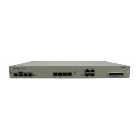
VOICE&DATA ROUTER PRODUCT OVERVIEW The device is a multifunction VoIP gateway with application in SIP Trunking, PBX IP Trunking and PSTN access for local IP telephony solutions. There are many usage applications available. It is a perfect solution to decrease costs of all your calls. PRODUCT FEATURES ... - Page 4 VOICE&DATA ROUTER Call permissions Calling Groups Ring Groups Call Pickup Announcement playback Remote management capabilities HTTP, SNMP, SSH, SCP, SFTP, TFTP Diagnostics functions SYSTEMS FOR VOICE AND DATA COMMUNICATION...
-
Page 5: Variants
ITX 495 01 GSM interface, optional 32 x analogue interface, optional 4 x BRI S0, optional 16 x BRI Uk0) ITX 495 01 . a b c d e f g h i j – Voice&Data Router X = 2 optic fibers... -
Page 6: Applications
VOICE&DATA ROUTER APPLICATIONS Voice & Data Router VoIP, TDM PBX (SW Asterisk) TDM - VoIP Gateway Signaling converter R2 MFC / ISDN DSS1 – SIP, Routing to another E1 if there is no more free capacity for simultaneous calls ... - Page 7 VOICE&DATA ROUTER Signaling converter R2 MFC / ISDN DSS1 – SIP Concentration of max. 4xE1/T1 (considering the limitation of max. number of simultaneous calls depending on the codec used) SYSTEMS FOR VOICE AND DATA COMMUNICATION...
- Page 8 VOICE&DATA ROUTER Multi Gateway (possibility to connect several customers and divide them) E1/T1 over Ethernet (IP) Extending SYSTEMS FOR VOICE AND DATA COMMUNICATION...
- Page 9 VOICE&DATA ROUTER SIP PROXY Server Local VoIP network SYSTEMS FOR VOICE AND DATA COMMUNICATION...
-
Page 10: Technical Specification
VOICE&DATA ROUTER TECHNICAL SPECIFICATION IP Telephony Protocols SIP – RFC 3261 SDP – RFC 2327 RTP – RFC 1889, RFC 2833, RFC 3389 ISDN Signaling Euro ISDN EDSS – 1/ETSI PRI/ NET5 ETS 300 011 (ISDN PRI UNI) ... - Page 11 DHCP support and capabilities Static Routing Management Web management – GUI Terminal access Local – control interface RS232 Remote – LAN/WAN interface (SSH protocol) Inoteska UniMan software SNMP v1/2c SYSTEMS FOR VOICE AND DATA COMMUNICATION...
- Page 12 VOICE&DATA ROUTER Power Supply 19”, 1U rack mount 85V – 260 V AC or -40V to -65V DC Frequency: 48Hz to 52 Hz 19”, 6U rack 48V DC Max.power consumption Max. 50W Dimensions 19”, 1U rack mountable 44 x 282 x 485 mm (h x d x w) Weight Approx.
-
Page 13: Operating Instructions
VOICE&DATA ROUTER OPERATING INSTRUCTIONS Operating Environment Install the device in a place where: Operating temperature: 0 C to 55 Storage temperature: -10 C to 65 Humidity: up to 80%, non-condensing Interfaces E1/T1 interface Ethernet 10/100Base-T interface RJ 45 connector RJ 45 connector 1 –... - Page 14 VOICE&DATA ROUTER Position No. 1 to 5: for FXS/FXO modules Position No. 6 to 8: for FXS/FXO/ E&M modules Analog connector 6. module E+M 7. module E+M 8. module E+M 1.module ab 2. module ab 3. module ab 4. module ab 5.
- Page 15 VOICE&DATA ROUTER Description of J2 connector Note: In description of connector, e.g. signal A23 means that it is a-wire from second module (first index) of third interface on module (second index). BRI interface 1 – Pins are connected as TE in default configuration. 2 –...
- Page 16 VOICE&DATA ROUTER BRID PR25-ON PR16 1-2 PR16 2-3 PR17 PR17 2-3 PR18 PR18 2-3 PR19 PR19 2-3 SYSTEMS FOR VOICE AND DATA COMMUNICATION...
- Page 17 VOICE&DATA ROUTER GSM interface Antenna connector: GSC connector coaxial SMT male 50R 6GHz CONTROL RS-232 connector CANNON - Female for RJ - 45 D09F cable RJ45 Cannon D09F + shield LED diodes Interface Led diode Led diode Status green yellow E1/T1 Not enabled Not connected...
-
Page 18: Management
Please contact the producer in case of difficulties! Inoteska Web Manager (GUI) provides simple and user-friendly interface for device configuration and supervision using web browser. Inoteska UniMan is universal software used for communication with Inoteska equipment which supports TCP / UDP protocol. -
Page 19: Web Manager
Initial screen serves for user (system administrator) login. Default login parameters: Username: admin Password*: inoteska *Change of password can be done in Options menu. After successful logging in Home page with device hardware configuration and identification will be displayed. - Page 20 VOICE&DATA ROUTER How to configure Voice&Data Router Step 1 Make basic system configuration IP setting – assign IP addresses to connect to LAN and WAN network. Configure DNS servers. In some cases it can be necessary to configure routing table for static IP routing. ...
- Page 21 VOICE&DATA ROUTER Most of the changes you made are being applied to your Voice&Data Router after click on Apply Changes filed in upper right corner. Some settings (e.g. change of IP settings, routing tables, date/time setting, etc.) are done automatically, without need to Apply Changes. If you want to end the work with Web Manager click on Logout in the upper right corner.
-
Page 22: Users Menu
VOICE&DATA ROUTER USERS MENU Users menu offers configuration of user extension lines. Voice&Data Router supports SIP users and analogue FXS users. Analogue users are optional and they depend on hardware configuration. SIP users SIP users configuration allows creating and managing user accounts for SIP phones. SIP users main screen displays table of configured SIP user extensions. - Page 23 VOICE&DATA ROUTER Host Options Host Type Voice&Data Router supports two methods how to connect to user SIP phone. Please select host type dynamic to use dynamic SIP registration procedure. Extension number and password from general section will be used for registration authentication. Static host type is intended for use as permanent static connection to the dedicated IP address.
- Page 24 VOICE&DATA ROUTER Codecs Here you can define allowed voice compression codecs in order of preference. Voice&Data Router supports following voice codecs: G.711 A-Law G.711 μ-Law G.729 Annex A/B G.726-32 G.723.1 iLBC Up to five different codecs with defined preference can be configured for every SIP user. VoIP Settings Qualify heck if the phone device is reachable.
- Page 25 VOICE&DATA ROUTER User’s Call Limit Enter maximal number of simultaneous calls permitted for this user. Voice&Data Router allows controlling SIP user’s access according to the IP addresses. There are no restrictions by default. Click Permit/Deny button in the SIP users’ list to configure range of IP addresses from which the user extension device can connect to Voice&Data Router.
- Page 26 VOICE&DATA ROUTER Analog users Main screen for analogue users displays table of all available analogue FXS user extensions. Analogue users are optional interfaces depending on hardware configuration of Voice&Data Router. Because FXS module has 4 ports we can have from 4 up to 32 analog users in the system (FXS module can occupy all 8 slots available on the analogue extension card).
- Page 27 VOICE&DATA ROUTER General Parameters Position This is analogue port position (number from 1 up to 32). Channel Internal channel number. Extension Extension number associated with this analogue user. Full Name A character-based display name used for caller identification (i.e. Bob Jones). Dial Plan Select dial plan to handle calls coming from user phone to Voice&Data Router.
- Page 28 VOICE&DATA ROUTER Polarity Reversal Enable/disable FXS line polarity reversal. When enabled every answer and hang-up of the remote party is signalized to the line by changing/switching its polarity. Rx Gain, Tx Gain Use these parameters for FXS line volume adjustment – transmit and receive gain or attenuation. Rx gain defines the level of voice received by Voice&Data Router from the FXS line and tx gain parameter defines the level of voice transmitted from Voice&Data Router to the FXS Line.
-
Page 29: Trunks Menu
VOICE&DATA ROUTER TRUNKS MENU Trunks menu offers trunks configuration. Voice&Data Router supports SIP trunks, E1/T1 trunks, BRI trunks (S0 or Uk0), analogue trunks (FXO and E&M) and GSM trunks. BRI, analogue and GSM trunks are optional and they depend on hardware configuration. SIP Trunks SIP trunks main screen displays table of all configured trunks. - Page 30 VOICE&DATA ROUTER Fromuser This allows you to overwrite the user name in the From and Contact SIP header fields of the INVITE request. It may be required by some providers for authentication. Fromdomain This allows you to set the domain in the From SIP header field of the INVITE request. It may be required by some providers for authentication Password Password to use for authentication.
- Page 31 VOICE&DATA ROUTER Codecs Here you can define allowed voice compression codecs in order of preference. Voice&Data Router supports following voice codecs: G.711 A-Law G.711 μ-Law G.729 Annex A/B G.726-32 G.723.1 iLBC Up to five codecs with defined preference can be configured for every SIP trunk. Caller ID This is the caller identification number that the trunk will try to use when making outbound calls.
- Page 32 VOICE&DATA ROUTER E1/T1 trunks Main screen for E1/T1 trunks displays table of available E1/T1 interfaces. There are always four E1/T1 ports in Voice&Data Router and unnecessary ports can be disabled Use Edit button to modify configuration of selected E1/T1 interface. E1/T1 trunk is configured in two steps.
- Page 33 VOICE&DATA ROUTER Line Mode Choose line mode 2,048 Mb/s line divided to 32 timeslots 1,544 Mb/s line divided to 24 timeslots. Note that CAS signaling is only available in E1 mode. It is also important to know that line mode changing resets the entire trunk configuration to default status.
- Page 34 VOICE&DATA ROUTER Slave 1 device is synchronized by the clock from the line Slave 2 device is synchronized by the clock from the line Slave 1 has higher priority than Slave 2. Longhaul RX, Longhaul TX These options enable to increase the device radius by setting the receiving/transmitting more sensitive.
- Page 35 VOICE&DATA ROUTER Accept CLEAR BACK Enable receiving of Clear-Back line signal from remote side. Channels Channels Choose available voice channels. E1 mode use channel range from 1 to 31. T1 mode use channel range from 1 to 24. Avoid of collision with signaling channel.
- Page 36 VOICE&DATA ROUTER Cyclic Enable cyclic search of available channel for outgoing call instead of sequential. Parameters Overlap Dial Enable/disable overlap dialing in ISDN signaling. If not enabled, complete called number in SETUP is required. E1 line with CAS signaling always uses overlap dialing. First Digit Timeout Enter timeout for the first digit to detect dialing hesitation during overlap dialing.
- Page 37 VOICE&DATA ROUTER BRI Trunks Voice&Data Router supports up to 16 BRI Uk0 interfaces or 4 BRI S0 interfaces. Initial screen for BRI trunks displays table of available interfaces according hardware configuration. BRI trunks are configured in two steps. First of all some essential settings are done. After that the configuration of all other details can be completed.
- Page 38 VOICE&DATA ROUTER Dial Plan Select dial plan to handle calls coming from this BRI line to Voice&Data Router. Dial plan consists of calling rules and it defines call routing scenario. Please see chapter Traffic Menu for more details about dial plans and calling rules configuration. Click Details button to continue with detailed configuration.
- Page 39 VOICE&DATA ROUTER Modes for S0 interface: network/provider side terminal/user (CPE) side Modes for Uk0 interface: network/provider side terminal/user (CPE) side Point-to-Multipoint Enable point-to-multipoint mode when Voice&Data Router is attached to an ISDN bus (more than one devices can be used at the CPE side).
- Page 40 VOICE&DATA ROUTER Add Incoming Charging If enabled charging units received from destination will be added to the charging units generated by Voice&Data Router according AOC table. Use Go Back button to return to general settings or click on Save button to confirm changes and store new setting.
- Page 41 VOICE&DATA ROUTER Analog Trunks Main screen for analogue trunks displays table of all available FXO interfaces. Analogue trunks are optional interfaces depending on hardware configuration of Voice&Data Router. Because FXO module/card has 2 ports we can have from 2 up to 16 analogue FXO trunks in the system (FXO module can occupy all 8 slots available on the analogue extension card).
- Page 42 VOICE&DATA ROUTER Parameters Echo Cancelation Enable/Disable echo cancelation for VoIP calls and select echo canceller tail length. Voice&Data Router supports echo canceller length from 8 ms up to 128 ms in step of 4 ms. Default echo canceller tail length is 64 milliseconds. Polarity Reversal Enable/disable polarity reversal detection on FXO trunk.
- Page 43 VOICE&DATA ROUTER GSM Trunks GSM trunks main screen displays table of available GSM interfaces. GSM trunks are optional interfaces depending on hardware configuration of Voice&Data Router. It is possible to have up to 12 GSM ports in the system. To modify GSM trunk configuration use appropriate Edit button in GSM trunks table. General Settings Name A unique label to help you identify GSM trunk.
- Page 44 VOICE&DATA ROUTER Echo Cancellation Enable/disable echo cancellation on GSM module to suppress acoustic echo from GSM network. Audio Level From GSM Configure speaker volume level in range from 0 to 99. This is voice level received by Voice&Data Router from GSM trunk. Default value is 91. To GSM Configure microphone volume level in range from 0 to15.
-
Page 45: Traffic Menu
VOICE&DATA ROUTER TRAFFIC MENU Traffic menu defines call routing between users and trunks. Call routing system of Voice&Data Router can be very easy but it can be also really complex depending on system functionality. It seams to be the most important part of the whole system which designates if Voice&Data Router works correctly or not. - Page 46 VOICE&DATA ROUTER Calling rules are divided into four tables User to User User to Trunk Trunk to User Trunk to Trunk You can create new empty calling rules group when you enter new unique label into the field New Calling Rules Group Name of appropriate table and click on the Create button.
- Page 47 VOICE&DATA ROUTER _NXXXXXX matches normal 7 digit number. _1NXXNXXXXXX would represent an area code plus phone number preceded by a one. _9011. matches any string of at least five characters that starts with 9011,but it does not match the four-character string 9011 itself. _9011! same as above but matches 9011 too.
- Page 48 VOICE&DATA ROUTER User to Trunk Details User to Trunk calling rules defines call routing from local user extensions outside of Voice&Data Router over the trunk interfaces. It can be call to PSTN, call to VoIP provider or call to cooperative gateway/PBX.
- Page 49 VOICE&DATA ROUTER Strip digits, and Prepend these digits before dialing These parameters allow modifying dialed number before the call is placed on the outbound trunk. You are allowed to strip specified number of digits from the front of dialed number and you can enter prefix string which will be prepended to the dialed number.
- Page 50 VOICE&DATA ROUTER Send to Destination: Local Destination Select call local destination. It is possible to select: Existing user extension – call will be routed directly to the selected user extension. Existing ring group – call will be routed to the selected ring group (group of user extensions which can ring simultaneously or sequentially, see Ring Groups for details).
- Page 51 VOICE&DATA ROUTER Change TON/NPI Enable to overwrite Type of Number and Numbering Plan Identification of dialed destination number before the call is routed to the selected outbound trunk. This option is applied only on trunk with ISDN signaling. Strip digits from Caller ID, and Prepend these digits to Caller ID These parameters allow modifying caller identification number before the call is placed on the outbound trunk.
- Page 52 VOICE&DATA ROUTER Dial Plans Main screen for dial plans configuration shows list of existing dial plans. It is divided into two tables Users Trunks Users’ dial plan can be assigned to the user extensions and trunks’ dial plan can be assigned to the trunk interfaces.
- Page 53 VOICE&DATA ROUTER Ignore Pattern This option tells Voice&Data Router to continue to provide a dial tone on an analogue line, even after the caller has dialed the indicated pattern. This will not work with SIP phones, as they usually do not send digits to the system as they are input but they are sent to Voice&Data Router all at once.
- Page 54 VOICE&DATA ROUTER AOC Tables Settings One of useful feature of Voice&Data Router is generation of charging information on E1/T1 lines. E1/T1 trunks with ISDN signaling use AOC supplementary service (AOC-D and AOC-E) and the trunks with CAS signaling uses billing pulses to generate charging information. Different parameters of call charging can be used for working days, weekend eventually for public holidays.
- Page 55 VOICE&DATA ROUTER Time tables define charging rules – frequency and number of charging units. Time table can divide the day into zones with different charging rules. Each time table defines charging rules separately for working day, weekend and public holiday. Charging rules allow setting of three time intervals for each call with different parameters.
- Page 56 VOICE&DATA ROUTER You can use the Create button to define new day time zone and the Edit Details button to change charging parameters of existing time zone. The Remove button can be used to delete selected time zone. Charging parameters: ...
- Page 57 VOICE&DATA ROUTER If charging interval is not set then charging units are generated only once for this time interval. Example 1 START LTI1 CHI1 CHU1 LTI2 CHI2 CHU2 CHI3 CHU3 0:00 This setting will generate regularly 1 charging unit every 10 seconds during the whole call. It does not matter what time you call.
- Page 58 VOICE&DATA ROUTER Note that correct functionality of generation of charging information depends on setting of Voice&Data Router system time. See Date and Time setting for more details about system time adjustment. SYSTEMS FOR VOICE AND DATA COMMUNICATION...
-
Page 59: Globals Menu
VOICE&DATA ROUTER GLOBALS MENU SIP settings SIP settings define common options of SIP protocol valid for all SIP users and SIP trunks. SIP protocol options are divided into the following groups: General Preferences Miscellaneous Registrations ... - Page 60 VOICE&DATA ROUTER Allow Transfers Enable/disable call transfers. Enable DNS SRV Lookups (on Outbound Calls) Enable DNS SRV lookups on outbound calls. Voice&Data Router only uses the first host in SRV records. Disabling DNS SRV lookups disables the ability to place SIP calls based on domain names to some other SIP users on the Internet.
- Page 61 VOICE&DATA ROUTER Send Remote Party ID This parameter specifies whether or not Voice&Data Router should send a Remote-Party-ID header. Generate In-Band Ringing Configuration of in-band ringing generation. yes – always send 180 Ringing (if it hasn't been sent yet) followed by 183 Session Progress and in-band audio tones.
- Page 62 VOICE&DATA ROUTER yes – always ignore info and assume NAT Server User Agent – use NAT mode only according to RFC3581 (;rport) never – never attempt NAT mode or RFC3581 support route – assume NAT, don't send rport Allow RTP Reinvite Configure default media path redirection.
- Page 63 VOICE&DATA ROUTER Register Attempts Number of outbound registration attempts before giving up. Setting to 0 means that Voice&Data Router will retry indefinitely. Enable Jitter Buffer Enable/disable the use of an RTP jitter buffer on the receiving side of a SIP channel. Registrations These global outbound SIP registrations can be useful for instances when Voice&Data Router needs to register multiple users/extensions to a single SIP proxy (provider).
- Page 64 VOICE&DATA ROUTER Host SIP registrar server address (IP address or host name) AuthUser User name used for the authentication. Use this setting only if it differs from the registration user name above. Password Password used for the authentication. Authentications Global credentials for outbound calls can be used when a proxy challenges Voice&Data Router for authentication.
- Page 65 VOICE&DATA ROUTER Realm Authentication realm. If it is matched to realm in proxy challenge, these authentication credentials override any credentials in user/trunk definition. Username Authentication user name for specified realm. Password Authentication password for specified realm. Jitter Buffer Force Jitter Buffer Force the use of the RTP jitter buffer on the receiving side of a SIP channel.
- Page 66 VOICE&DATA ROUTER SYSTEMS FOR VOICE AND DATA COMMUNICATION...
- Page 67 VOICE&DATA ROUTER RTP/UDPTL Settings RTP and UDPTL protocol configuration. Here you can define port range allocated for voice (RTP) and T.38 fax (UDPTL) transmission. Start Port First port number reserved for RTP/UDPTL protocol. End Port Last port number reserved for RTP/UDPTL protocol. Note that only odd port numbers (half of the allocated range) can be used for RTP or UDPTL stream.
- Page 68 VOICE&DATA ROUTER Call Groups Call groups can group together outgoing trunks. Call group joins multiple TDM trunks (E1/T1, analogue and GSM) to a single group for outgoing calls (grouping of VoIP trunks is not supported). Such group can be used in the calling rules as the call destination (user to trunk or trunk to trunk). Outgoing call is placed on the first idle channel which is found according method defined in call group configuration.
- Page 69 VOICE&DATA ROUTER SYSTEMS FOR VOICE AND DATA COMMUNICATION...
- Page 70 VOICE&DATA ROUTER Ring Groups Ring groups join user extensions to the single group that can ring a group of phones simultaneously, stopping when any one of them is picked up. Such group can be used in the calling rules as the call destination (user to user or trunk to user).
- Page 71 VOICE&DATA ROUTER Available Users List of available user extensions, which can be added to the ring group. Strategy Define what ringing strategy is used Ring All Simultaneously – all phones are ringing at once Ring in Order – ring group phones are ringing step by step Seconds to Ring Each Member Enter time how long to ring phones in the ring group.
- Page 72 VOICE&DATA ROUTER Carriers Alternative carriers supporting two-stage dial service can be used to lower communication costs. Two- stage dialing allows you to dial carrier access number first (this is usually low-tariff number). And then after call answer, DTMF tones are used to authenticate and dial destination number. Two step calls over alternative carrier can be enabled in the calling rules (user to trunk or trunk to trunk) and Voice&Data Router makes such calls automatically so it appears like ordinary call.
- Page 73 VOICE&DATA ROUTER Permissions Permissions are used to limit outgoing communication of local users. Every user extension has assigned permission group. Permission group is a collection of permission flags which can be assigned to the calling rules (user to user or user to trunk). User is allowed to make a call only if his permission group includes call permission flag assigned to calling rule for dialed number.
- Page 74 VOICE&DATA ROUTER check boxes to select call permission flags for each group. Every group can have symbolic name to easier understanding. User permission group with all call permission flags checked is the most privileged group. There are no restrictions for the user with such group because all permission flags are allowed. On the other hand user permission group that does not have selected any call permission flag can be limited only for incoming calls.
- Page 75 VOICE&DATA ROUTER Services Codes Users’ service codes configuration. Here you can define dial codes for activation, deactivation or execution of users’ services form the phone. Note that the user is allowed to use configured service codes only if his dial plan includes service codes (see dial plan configuration).
- Page 76 VOICE&DATA ROUTER CDR Settings CDR – Call Detail Records – save information about Voice&Data Router calls. CDR records are stored in the text file as comma separated values. CDR Note Here, you can enter optional string that will be added to every CDR. CDR User to User Enable to log CDR for local calls between Voice&Data Router users.
- Page 77 VOICE&DATA ROUTER You can use link Download CDR File to download CDR file from Voice&Data Router for additional processing. SYSTEMS FOR VOICE AND DATA COMMUNICATION...
- Page 78 VOICE&DATA ROUTER Announcement Settings Announcement management is used for configuration of announcement files for call routing. New announcement file can be recorded from user phone or existing file can be uploaded. Only files of supported format can be uploaded. Voice&Data Router uses Microsoft WAVE files with following format Sample rate 8 kHz...
- Page 79 VOICE&DATA ROUTER Use the Record File button to switch to announcement recording form. Voice&Data Router allows you to record your voice message file from your phone. You need to select one user extension, enter new announcement name and click on the Start button. Voice&Data Router rings selected user extension. Pick up the phone, wait for beep sound and then say your new voice message.
- Page 80 VOICE&DATA ROUTER CAS National Variants There are various country-specific variants of E1 CAS signaling protocol. Voice&Data Router offers set of configurable parameters to adapt CAS signaling to specific requirements of each installation. Device is supplied with several predefined variants of CAS signaling you can use and you are allowed to customize these predefined variants for your needs or to create your own variant.
- Page 81 VOICE&DATA ROUTER Backward Signals Line signals for backward direction (signals sent by the terminating/destination point). Seizure ACK Line seizure acknowledge signal. Answer Line answer signal. Clear-Back Clear-Back signal – normal call clearing initiated by called party after call answer. Forced Release Forced Release signal –...
- Page 82 VOICE&DATA ROUTER End of ANI Indication of the end of ANI (Automatic Number Identification) number. ANI not Available ANI number is not available – ANI restriction. Group II Secondary forward signals are used to provide calling party category. National Subscriber Calling party is subscriber without priority.
- Page 83 VOICE&DATA ROUTER International Operator Calling party is international operator. International Data Calling party is international data transmission equipment. Group A Primary backward signals are used especially to collect DNIS and ANI digits from the calling party. Send Next DNIS Digit Request to send next DNIS digit.
- Page 84 VOICE&DATA ROUTER Address Completed, Switch to Group B Indication of the complete DNIS number and switch over to reception of group B signals. Network Congestion Call failure, network congestion indication. Send Calling Party Category Request to send calling party category. Immediate Accept Indication of the complete DNIS number and immediate call acceptation.
- Page 85 VOICE&DATA ROUTER Repeat All DNIS Digits and Switch to Group A Request to repeat complete DNIS number form the beginning and switch over to reception of group A signals. Send Next DNIS Digit and Switch to Group A Request to send next DNIS digit and switch over to reception of group A signals. Send Previous DNIS Digit and Switch to Group A Request to repeat last DNIS digit and switch over to reception of group A signals.
- Page 86 VOICE&DATA ROUTER Switch to Group A on End of ANI during Group C Enable switch over to reception of group A signals when end of ANI number indication is sent during reception of group C signals. Billing Pulse after Answer Enable generation of one billing pulse automatically after call answer.
- Page 87 VOICE&DATA ROUTER Max.Forward MFC/R2 Signal Off-time (T2) Maximum time a forward MFC/R2 signal can be off, from the outbound perspective. Inbound Side Compelled Cycle Timer (T3) Maximum time a whole compelled MFC/R2 cycle can take, from the inbound perspective. MFC/R2 Backward Non-compelled Pulse Length Duration of non-compelled MFC/R2 signaling pulse in backward direction.
-
Page 88: System Menu
VOICE&DATA ROUTER SYSTEM MENU IP settings IP settings provide basic configuration of the Ethernet interfaces LAN and WAN (IP address assignment, MAC address modification, DNS setting, etc). Voice&Data Router is supplied with the following default setting: Mode static static IP Address 192.168.1.100 10.1.1.100 Mask... - Page 89 VOICE&DATA ROUTER MAC Address Check Default if you want to use Ethernet hardware address assigned by producer. If you need to overwrite hardware Ethernet address for some reason to suit your preference then uncheck Default and enter new address as colon separated hexadecimal numbers (e.g. 00:50:C2:38:76:80). Modified MAC address will be applied only after reboot of Voice&Data Router.
- Page 90 VOICE&DATA ROUTER Routing Tables Routing tables define rules for static IP routing. In most cases it is enough to configure basic IP settings and no additional rules for IP routing are necessary. Here you can configure additional gateways for routing to the target address (host or network). Use the Create New button to add new route to the routing table.
- Page 91 VOICE&DATA ROUTER SNMP SNMP (Simple Network Management Protocol) is an application layer protocol used in network management systems to monitor network-attached devices for conditions that warrant administrative attention. On Voice&Data Router, SNMP agent is running to allow administrators to remotely manage device status and configuration.
- Page 92 VOICE&DATA ROUTER Use the Add button to define new SNMP traphost. Click Edit button to modify selected SNMP traphost. To remove existing traphost use the Delete button. Traphost IP address or the host name of the traphost. Administrating application’s host address should be inserted here.
- Page 93 VOICE&DATA ROUTER Firewall Voice&Data Router firewall function can protect LAN network and Voice&Data Router itself from unauthorized users of other networks. It is recommended to activate firewall if Voice&Data Router is used in function of access data router or if it is connected directly to the Internet on public address. Firewall implementation in Voice&Data Router allows: ...
- Page 94 VOICE&DATA ROUTER Input firewall rules define condition to match incoming packet and the policy. Input packets which satisfy the rule condition are accepted/dropped according rule policy. If packet does not match condition of any rule then global policy is applied. Protocol Select the IP transport protocol of incoming packet to apply the rule.
- Page 95 VOICE&DATA ROUTER Src Address Enter packet source address. Source address condition can restrict/allow packets from certain IP addresses. You can specify single IP address or network IP address with mask. The mask can be either a network mask or a plain number, specifying the number of 1's at the left side of the network mask.
- Page 96 VOICE&DATA ROUTER either a network mask or a plain number, specifying the number of 1's at the left side of the network mask. Thus, a mask of 24 is equivalent to 255.255.255.0. Dst Address Enter packet destination address. Destination address condition can restrict/allow packets addressed to specific IP addresses.
- Page 97 VOICE&DATA ROUTER forwarding or port mapping. You can define set the rules for LAN destination address translation. Click on the Add New button if you want to create new destination NAT rule. Use the Edit button to modify existing rule. Use the Delete button to remove selected rule and the Delete All button to remove all the rules from the list.
- Page 98 VOICE&DATA ROUTER Options Use Change password to change password of active user (admin) for access to Voice&Data Router Web Manager. Password should be at least 4 characters long. For password changing type your new password in the Enter New Password text field and confirm it in the Retype New Password field. New password is activated after click on the Update button and you are automatically redirected to the initial login screen to re-login with new authentication.
- Page 99 VOICE&DATA ROUTER SYSTEMS FOR VOICE AND DATA COMMUNICATION...
- Page 100 VOICE&DATA ROUTER Backup and Restore Voice&Data Router allows you to manage configuration data backups. You can create and store backup of actual Voice&Data Router configuration. It is possible to return back to the stored configurations at any moment in the future. You can also download configuration backups to archive them out of the device.
- Page 101 VOICE&DATA ROUTER Firmware Update Voice&Data Router supports three possibilities how to update firmware TFTP protocol download HTTP protocol download File upload Use TFTP Server Check this option to use TFTP protocol to download firmware update file. Enter TFTP URL address – server address with path to the update file, into the input field and click on Update Firmware button.
- Page 102 VOICE&DATA ROUTER Date and Time Voice&Data Router system time adjustment. Date and Time Setting Date, Time Current date and time. Get Device Time Click to read current system time from Voice&Data Router and refresh displayed date and time. Get Computer Time Click to get current system time of your PC and refresh displayed date and time (can be used to synchronize Voice&Data Router with your PC).
- Page 103 VOICE&DATA ROUTER Update interval Select interval of automatic clock synchronization. Hourly every hour Daily every day at 2:25 am Weekly every Sunday at 2:47 am Configuration changes apply immediately after clicking on the Save & Apply button. There is no need to activate standard Apply Changes function.
-
Page 104: Diagnostics Menu
VOICE&DATA ROUTER DIAGNOSTICS MENU Port Status Port status displays actual status of selected ports. Actual status is read from Voice&Data Router after pressing Display Status button. If Enable Auto Updating is checked status is updated automatically circa every 3 seconds. You can display status of the following ports/channels: ... - Page 105 VOICE&DATA ROUTER Active Services Use active services function to display actual status of users’ services. It displays list of all users with active services like Do Not Disturb and Call Forwarding. You can use Delete User and Delete All buttons to deactivate services for selected user eventually for all users.
- Page 106 VOICE&DATA ROUTER Identification Identification provides basic hardware information about Voice&Data Router. BASIC section information is read from permanent memory which is programmed during device production. Here you can find information such as device type – product code number, serial number, date of production, hardware interfaces, etc.
- Page 107 VOICE&DATA ROUTER System Logs Voice&Data Router stores operation logs in the file system. Voice&Data Router logs management is divided into two parts: Asterisk Log Files System Log Files Asterisk Log Files cover log messages from the Asterisk voice communication system application. It is possible to enable/disable Asterisk logging, set logging level and display stored logs.
- Page 108 VOICE&DATA ROUTER SYSTEMS FOR VOICE AND DATA COMMUNICATION...
- Page 109 VOICE&DATA ROUTER CLI Emulator CLI emulator provides you access to Command Line Interface of internal Asterisk. It allows you to execute CLI commands you enter in the CLI Command field. Use command “help” to display all available CLI commands. To display brief command description you can use “help”...
- Page 110 VOICE&DATA ROUTER Debug messages Debug messages can log GUI manager functionality. Use the Start DEBUG and Stop DEBUG buttons to control Voice&Data Router GUI manager debugging. SYSTEMS FOR VOICE AND DATA COMMUNICATION...
- Page 111 VOICE&DATA ROUTER System Status System status shows actual status of Voice&Data Router. It involves actual system time and device running time, usage of hardware resources (CPU, memory, file system) and information about software version. SYSTEMS FOR VOICE AND DATA COMMUNICATION...
- Page 112 VOICE&DATA ROUTER File Editor File editor provide direct access to selected configuration files of Voice&Data Router. In this way you are able to configure nonstandard functions or functions not supported by Web Manager. Files you can access are listed in the Config Files list on the right side. Selected file is displayed on the screen.
-
Page 113: Specials Menu
VOICE&DATA ROUTER SPECIALS MENU AOC Web Update Domain Name or IP Address Name or address of web server where AOC files are saved Working Directory Name Directory name on server where AOC files are saved (item can be blank if files are in server main directory) Periodicity Periodicity of AOC files correctness control, it is possible to choose either time interval (every 1, 4, 6 or... -
Page 114: Uniman
UDP connection can be used to communicate with local devices. You do not need to know device IP address – UniMan is able to search for available Inoteska equipments. This access type can be used only if the conditions stated below are met: Device is connected in network ... - Page 115 VOICE&DATA ROUTER UDP port 3864 must be enabled on PC Device must have default gateway configured Device must be attached by default Ethernet interface 1. Set Access type to UDP. 2. Click on Connect. All the devices connected in network will be displayed.
-
Page 116: Setting Of Password
VOICE&DATA ROUTER SETTING OF PASSWORD To have access to the Voice&Data Router configuration, password authentication is required. Default password is inoteska. You can manage UniMan password using main menu Options/Password. New login New login with new password. Change password of device Change of default password. -
Page 117: Configuration Files Editor
VOICE&DATA ROUTER CONFIGURATION FILES EDITOR Configuration files editor provides access to the device configuration. Just now there is available only network configuration for Voice&Data Router. To open configuration editor click on the speed button Config files editor or use main menu Communication/Config files editor. - Page 118 VOICE&DATA ROUTER Network Setting – GUI GUI interface for network setting is available from the configuration file editor – Network Graphic or directly form main window using speed button Remote control & IP/Ethernet setting or from main menu Communication/Remote control IP/Ethernet setting. MAC Address Enter ‘DEFAULT’...
-
Page 119: Diagnostics
VOICE&DATA ROUTER DIAGNOSTICS Use diagnostic window to monitor system status and status of each interfaces. Diagnostic is activated by the speed button Diagnostic or from the main menu command – Communication/Diagnostic. Type of diagnostic list on the left side of the diagnostics shows index of items that can be monitored. Double click on the selected item will display information of actual status. -
Page 120: Listing Messages
VOICE&DATA ROUTER LISTING MESSAGES This function allows making online logs of Voice&Data Router call switching. You can access listing window by clicking on the speed button Listing messages or by using main menu commond – Communication/ Listing messages. On the Setting card you can configure logging filter – selection of interfaces and protocols to monitor and also monitoring level. - Page 121 VOICE&DATA ROUTER SYSTEMS FOR VOICE AND DATA COMMUNICATION...
-
Page 122: Identification
VOICE&DATA ROUTER IDENTIFICATION Identification provides basic hardware information about Voice&Data Router. To open identification window use speed button Identification or main menu command – Communication/Identification. BASIC section information is read from permanent memory which is programmed during device production. Here you can find information such as device type – product code number, serial number, date of production, hardware interfaces, etc. -
Page 123: Terms Of Sale
Delivery: Standard delivery time is max. 6 weeks from the signing of the purchase order or after mutual agreement. Contact: Inoteska s.r.o. Tel.: + 421 44 5567 911 Podtureň-Roveň 221 Fax: + 421 44 5221 519 Liptovský...
Need help?
Do you have a question about the ITX 495 01 and is the answer not in the manual?
Questions and answers