Table of Contents
Advertisement
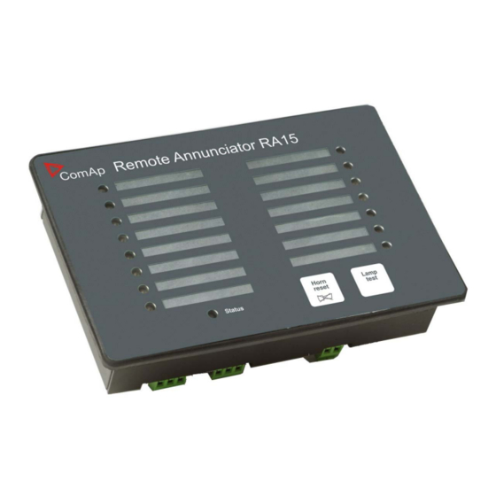
IGL-RA15
SW version 2.0.0
1 Document information
2 System overview
3 Installation and wiring
4 Technical data
Copyright © 2018 ComAp a.s.
Written by Roman Taragel
Prague, Czech Republic
ComAp a.s., U Uranie 1612/14a,
170 00 Prague 7, Czech Republic
Tel: +420 246 012 111
E-mail: info@comap-control.com, www.comap-control.com
Remote annunciator
3
6
10
15
Global Guide
Advertisement
Table of Contents

Summary of Contents for ComAp IGL-RA15
-
Page 1: Open
SW version 2.0.0 1 Document information 2 System overview 3 Installation and wiring 4 Technical data Copyright © 2018 ComAp a.s. Written by Roman Taragel Prague, Czech Republic ComAp a.s., U Uranie 1612/14a, 170 00 Prague 7, Czech Republic Global Guide Tel: +420 246 012 111 E-mail: info@comap-control.com, www.comap-control.com... -
Page 2: Table Of Contents
2.5 Signal LEDs 2.5.1 PWR LED 2.6 Horn 2.7 Lamp and horn test 2.8 LED labels 3 Installation and wiring 3.1 Rubber seal installation 3.2 Opening the IGL-RA15-FPC 3.3 Terminals and dimensions 3.4 Recommended wiring 4 Technical data IGL-RA15 2.0.0 Global Guide... -
Page 3: Document Information
InteliDrive-Mobile (Logger) InteliDrive-Lite (Lite, Marine, FPC, IPC, IPU, EM) IGL-RA15 is equipped with a fully configurable tri color (red, orange, green) LED for intuitive operation together with high functionality. Note: The FPC unit does not have any buttons, so all adjustment bellow needs to be adjusted by opening the cover and pressing the micro switches of the buttons manually, see Opening the IGL-RA15-FPC on page 11 1.3 Legal notice... - Page 4 Official version of the ComAp’s End User's Guide/Manual is the version published in English. ComAp reserves the right to update this End User's Guide/Manual at any time. ComAp does not assume any responsibility for its use outside of the scope of the Terms or the Conditions and the License Agreement.
-
Page 5: Document History
• The SNMP protocol (port UDP/161) version 1,2 is not encrypted. Thus it is intended to be used only in closed private network infrastructures. • Avoid exposing the port UDP/161 to the public Internet. 1.4 Document history Revision Number Related SW Version Date 2.0.0 10.07.2019 2.0.0 29.5.2018 6 back to Document information IGL-RA15 2.0.0 Global Guide... -
Page 6: System Overview
Set the address up by pressing Horn reset. The number of red luminous LEDs means the CAN1 addresses (two for addresses 1+2, four for addresses 3+4, six for addresses 5+6 and eight for addresses 7+8) Press Lamp test IGL-RA15 2.0.0 Global Guide... -
Page 7: Leds Color Change
Each LED color is adjusted independently of controller output settings. If controller output 1 is set as “Common Shutdown” it doesn’t mean red LED1 color for IGL-RA15. The LEDs color can by adjust by following steps: Switch to programming mode (Hold the Horn reset and Lamp test when unit is powering on) -
Page 8: Pwr Led
The labels are slipped to slots in the front foil. The slot openings are located on the upper edge of the front panel. The RA15 module is shipped with one A4 sheet of foil for printing of labels. IGL-RA15 2.0.0 Global Guide... - Page 9 Note: Not available in FPC version (EM2FPCRAEAA) 6 back to System overview IGL-RA15 2.0.0 Global Guide...
-
Page 10: Installation And Wiring
3 Installation and wiring 3.1 Rubber seal installation 3.2 Opening the IGL-RA15-FPC 3.3 Terminals and dimensions 3.4 Recommended wiring 6 back to Table of contents 3.1 Rubber seal installation The correct way to install the rubber sealing is shown on the pictures below. -
Page 11: Opening The Igl-Ra15-Fpc
3.2 Opening the IGL-RA15-FPC This is just for authorized acces: 1. Remove the screws 2. Bottom side IGL-RA15 2.0.0 Global Guide... - Page 12 3. You can directly press the micro switches on PCB IGL-RA15 2.0.0 Global Guide...
-
Page 13: Terminals And Dimensions
3.3 Terminals and dimensions IGL-RA15 IGL-RA15-FPC IGL-RA15 2.0.0 Global Guide... -
Page 14: Recommended Wiring
3.4 Recommended wiring Note: The shielding of the CAN bus cable has to be grounded at one point only! see Technical data on page 15 for recommended CAN bus cable type. 6 back to Installation and wiring IGL-RA15 2.0.0 Global Guide... -
Page 15: Technical Data
36 VDC 3105A Paired EIA Industrial RS485 cable voltage LAPP CABLE (see www.lappcable.com): Unitronic BUS DeviceNet Trunk Cable Unitronic BUS DeviceNet Drop Cable Unitronic BUS CAN Unitronic-FD BUS P CAN UL/CSA 6 back to Table of contents IGL-RA15 2.0.0 Global Guide...
Need help?
Do you have a question about the IGL-RA15 and is the answer not in the manual?
Questions and answers