
Summary of Contents for A.T.I.B. INTEGRAL SIDESHIFT 122
- Page 1 INSTRUCTIONS MANUAL FOR USE INTEGRAL SIDESHIFT TYPE 122 atib.com I-D02-01-43 – Rev.2...
-
Page 2: Table Of Contents
INDEX INTEGRAL SIDESHIFT TYPE 122 WARNING READ THIS MANUAL VERY CAREFULLY BEFORE STARTING-UP THE MACHINE. INDEX ..............................1 1 SAFETY RULES ..........................2 2 INTRODUCTION ..........................3 Use and upkeep of this manual ..................3 Description of equipment ....................4 3 INSTALLATION .......................... -
Page 3: Safety Rules
1 SAFETY RULES 1 SAFETY RULES Don’t cross the mast Don’t carry passengers Swing 75mm March Don’t pass under the load Pag. 2 di 26... -
Page 4: Introduction
2 INTRODUCTION 2 INTRODUCTION 2.1 Use and upkeep of this manual This “User Manual” (hereinafter referred to as Manual) is supplied together with the A.T.I.B. – INTEGRAL SIDESHIFT TYPE 122 pursuant the CE DIRECTIVE 2006/42/CE date 17/05/2006 and amendments. The information contained here are imperative for the correct use of the attachment and must be known by the personnel who install, use, maintain and repair it. -
Page 5: Description Of Equipment
2 INTRODUCTION 2.2 Description of equipment All the A.T.I.B. – INTEGRAL SIDESHIFT TYPE 122 are identified by means of a sticky identification label ( Pag. 4 di 26... - Page 6 2 INTRODUCTION ) position of identification label on equipment (Picture 1), always refer to serial number. POSITION LABEL Picture 1 TTYPE 11. MAX. TORQUE daN m 8. NOMINAL CAPACITY kg/mm CODE 9. CLAMPING CAPACITY kg/mm SERIAL N° YEAR OF MANUFACTURE 10.
- Page 7 2 INTRODUCTION 2. CODE It identifies the equipment order code. 3. SERIAL N° It progressively identifies the individual equipment. The series number has been stamped should the tag go missing or be damaged. Always refer to the series number for any kind of information. 4.
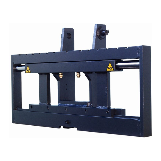
- Page 8 2 INTRODUCTION This equipment must be installed directly on the forklift mast, and connected to the distributor by means of a hydraulic circuit; the attachments must then be applied to it (forks, clamps ecc.). The sideshifting movement through cylinder hydraulic actioning. The coupling components of the fork holding plate are manufactured in compliance with the ISO 2328 norm.
-
Page 9: Installation
3 INSTALLATION 3 INSTALLATION Verify the nominal capacity of equipment To check the nominal capacity of equipment, consult the identification label Tab 1 a pag.5) WARNING Make sure that the operator of the forklift is aware of the maximum capacity of the attachments, so as NOT to pose a danger to himself and to the people who work in his vicinity. -
Page 10: Installation
3 INSTALLATION 3.1 Installation 3.1.1 Installation the attachment without welded brackets 1. Before installation, verify the condition of the fork carriage, WITHOUT BRACKET ensuring that it is not deformed. 2. Also make sure that the profiles of the fork holding plate are not deformed, in order to allow a good coupling with the equipment. - Page 11 3 INSTALLATION 5. Remove the brackets from the original fork holder plate and any chain hooks. 6. Remove the movable frame D with belts E appropriately sized for the weight of the equipment (Picture 3), lifting it with an overhead crane or with a hoist of sufficient capacity. Picture 3 7.
- Page 12 3 INSTALLATION 8. Mount the upper slides B and lower slides C in their seats (Picture 4). Picture 4 9. Grease the lower part of the mobile frame, where the slides will slide C (Picture 4). Pag. 11 di 26...
- Page 13 3 INSTALLATION 10. Mount the movable frame D from the top of the equipment with the aid of bands appropriately sized to the weight of the equipment (E) by an overhead crane or with a hoist of sufficient capacity (Picture 5). Picture 5 11.
- Page 14 3 INSTALLATION 12. Lubricate the sliding parts using the special grease nipples (Picture 14 and pag. 25). 13. Couple the sliding rollers of the mast to the pins made on the bracket (Picture 7), in this picture, as in the following, bearings, bracket and masts indicated are purely indicative, with the sole purpose of showing the correct assembly of the equipment.
- Page 15 3 INSTALLATION 15. Install the equipment in the mast by inserting the rollers in the special sliding guides and fasten the chains in the holes in the sides according to the procedures provided by the manufacturer of the mast (Picture 8) Picture 8 16.
-
Page 16: Installation The Attachment With Welded Brackets
3 INSTALLATION 3.1.2 Installation the attachment with welded brackets 1. Before installation, verify the condition of the fork holding plate, making sure that the lower profile is free of roughness that could WELDED BRACKETS compromise the sliding of the lower slides. 2. - Page 17 3 INSTALLATION 7. Install the equipment in the mast by inserting the rollers into the appropriate sliding guides and fasten the chains in the holes in the brackets according to the methods provided by the mast manufacturer (Picrure 10). Picrure 10 8.
-
Page 18: Use Rules
4 USE RULES 4 USE RULES Before using the equipment, check the tightness of the pipes and the correctness of assembly and connection by performing about ten preliminary operations. When using the equipment, it is necessary to follow the instructions listed below: 1. - Page 19 4 USE RULES Every ATIB attachments are projected and constructed according to a load positioned (as regards its centre of gravity) at a certain distance from vertical part of the fork. If you need to increase the distance of the center of gravity as regards vertical part of the fork you have to reduce the weight of the load.
- Page 20 4 USE RULES To check the nominal capacity of the combination forklift – attachment ask the producer of the forklift. The condition of the soil, the quickness of the movement of the load and the lifting height can affect the hold of the load and must be taken into consideration as regards specific occasions.
-
Page 21: Periodic Maintenance
5 PERIODIC MAINTENANCE 5 PERIODIC MAINTENANCE Failure to adhere to the norms and established times for maintenance operations, will be detrimental to the good functioning of the equipment and will annul the guarantee conditions. All maintenance operations must be carried out with the forklift motionless and the hydraulic circuit not activated, perimeter the entire maintenance area, using the necessary protective devices and, if it is necessary to disassemble the cylinders, always using a tray or container to recover the oil still present in the cylinder itself. -
Page 22: Maintenance Every 1000 Hours
5 PERIODIC MAINTENANCE 5.3 Maintenance every 1000 hours 1. Check the condition of upper and lower sliding devices if an excessively worn component is found, it is recommended to replace the entire assembly of the component in question. 2. Also carry out the operations listed in the previous point (Points 06.01 and 06.02 pag.20). 5.4 Maintenance every 2000 hours 1. -
Page 23: Disassembly Procedure
6 DISASSEMBLY PROCEDURE 6 DISASSEMBLY PROCEDURE 6.1 Cylinder removal 1. Relieve the pressure of the hydraulic system. 2. Remove the movable frame with belts appropriately sized as indicated in Picture 3, pag. 10. 3. Remove the elastic ring A and extract the stem B which will come out of its seat together with the cap C. - Page 24 6 DISASSEMBLY PROCEDURE 4. Replace the worn seal (Picture 13). Picture 13 Number Code Descrizione Description A5001103 O-ring O-ring A5111168 Guarnizione Seal A5309035 Raschiatore Scraper ring Tab 3 5. Reassembly the cylinder, follow the previous steps in backwards. Pag. 23 di 26...
-
Page 25: Breakdowns And Solutions
7 BREAKDOWNS AND SOLUTIONS 7 BREAKDOWNS AND SOLUTIONS 7.1 Breakdowns and solutions FAILURE CAUSE SOLUTION Check the tank level and the pump Low oil flow Bottlenecks in the system: Search and delete them Mechanical deformations of some parts Repair or replace Worn cylinder seals Replace Presence of air in the hydraulic system... -
Page 26: Lubricate
7 BREAKDOWNS AND SOLUTIONS 7.2 Lubricate 1. Lubricate the sliding parts using the special grease nipples (Picture 14). 2. Lubricate the slide and relative scroll bar (Picture 14). Picture 14 Pag. 25 di 26... - Page 27 A.T.I.B. S.r.l. Via Quinzanese snc 25050 Dello (BS) ITALIA Tel: +39 030 9771711 info@atib.com follow us atib.com I-D02-01-43 – Rev.2...