Advertisement
Quick Links
BASR
Versatile BACnet/IP Controller/Gateway
ATTENTION: The BASremote User Manual can be downloaded at
https://www.ccontrols.com/pdf/TD0403000M3.pdf
INTRODUCTION
The BASremote series provide the system integrator a flexible building block
when integrating diverse building automation protocols or when expanding
the number of points in a building automation system. By supporting open
system protocols such as BACnet
the BASremote series is easily adaptable. For small systems, it can operate
stand-alone. For larger systems, it can communicate to supervisory
controllers over Ethernet. Depending upon the model, the BASremote has
the flexibility to provide the following:
Versatile Control Device — remote I/O, router, gateway and controller
•
Web-page configuration
•
BACnet/IP Remote I/O
•
Modbus TCP Remote I/O
•
Modbus Serial to Modbus TCP Router
•
Modbus Serial to BACnet/IP Gateway
•
Modbus Master to Attached Modbus Slaves
•
Powered by Sedona Framework™ Controller
•
Power over Ethernet (PoE)
•
Customisable web pages
Flexible Input/Output — expandable by adding modules
•
Six universal input/output points web-page configurable
•
Two relay outputs
•
Thermistors, voltage, current, contact closure and pulse inputs
Voltage, current and relay outputs
•
•
2-wire Modbus Serial Expansion port
•
2-wire expansion port for up to three expansion I/O modules
CONTEMPORARY
INSTALLATION GUIDE
(Version 3.5.x and higher)
, Modbus and Sedona Framework
®
BAS
C
O NTR LS
remote
SOX,
™
O
®
Advertisement

Summary of Contents for Contemporary Controls BASR Series
- Page 1 BASR remote Versatile BACnet/IP Controller/Gateway INSTALLATION GUIDE (Version 3.5.x and higher) ATTENTION: The BASremote User Manual can be downloaded at https://www.ccontrols.com/pdf/TD0403000M3.pdf INTRODUCTION The BASremote series provide the system integrator a flexible building block when integrating diverse building automation protocols or when expanding the number of points in a building automation system.
- Page 2 The BASremote Master provides the ultimate in flexibility. It can be used for expansion I/O at remote locations where an Ethernet connection exists. Its built-in router and gateway capabilities address unique integration needs where more than one communications protocol is involved. It can operate as a function block programmable controller with its resident Sedona Framework Virtual Machine.
- Page 3 TRADEMARKS Contemporary Controls, ARC Control, ARC DETECT, BASautomation, EXTEND-A-BUS, RapidRing, and CTRLink are trademarks or registered trademarks of Contemporary Control Systems, Inc. Specifications are subject to change without notice. Other product names may be trademarks or registered trademarks of their respective companies. BACnet is a registered trademark of the American Society of Heating, Refrigeration, and Air-Conditioning Engineers, Inc.
-
Page 4: Specifications
SPECIFICATIONS Electrical BASR-8M/P BASR-8M BASR-8X (± 10%) Input voltage: 24 V 24 V 48 V 24 V 24 V Input power: 10 W 10 W 17 VA 17 VA Input frequency: 47–63 Hz 47–63 Hz (All modules intended for use with Class 2 circuits only.) Loop Supply +24 VDC, 150 mA max +24 VDC, 150 mA max... -
Page 5: Led Indicators
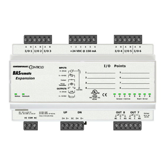
Environmental Operating temperature: 0°C to +60°C Storage temperature: –40°C to +85°C Humidity: 10% to 95%, non-condensing Universal I/O (Channels 1–6) — Software configurable All protected for: short-circuit and over-voltage up to 24 VAC Analog inputs: 10 bit resolution, 0–10 V or 0–20 mA (Input impedance 100 kΩ... - Page 6 roduct mages anel ountIng emoved Reset Switch Figure 2 — BASremote Master Image Figure 3 — BASremote Expansion Image TD040300-0IL...
- Page 7 roduct mage anel ountIng emoved Reset Switch Figure 4 — BASremote PoE Image echanIcal anel ountIng IsPlayed Figure 5 — BASremote Dimensional Drawing for All Models TD040300-0IL...
-
Page 8: Installation
INSTALLATION The BASR is intended to be mounted in an industrial enclosure or wiring closet on 35-mm DIN-rail or panel-mounted with screws (not provided). The panel-mounting tabs are packaged in a plastic bag within the shipping box. To use these tabs, Figure 6 illustrates how the two studs of each tab are press fitted into their respective holes in opposing corners of the case. - Page 9 Modbus Serial Bus Connections The Modbus serial expansion port (MB) on the BASremote Master module is non-isolated EIA-485 compatible. When connecting to other non-isolated devices, care must be exercised to ensure that all non-isolated Modbus devices share the same ground reference (COM) with the BASremote Master module. This is usually accomplished by sharing the same power source.
- Page 10 ablIng onsIderatIons When attaching cables to the BASR, Table 1 should be considered. Function Signalling & Minimum Required Maximum Data Rate Cable Segment Distance Ethernet 10BASE-T Category 3 UTP 100 m (328 ft) 10 Mbps Ethernet 100BASE-TX Category 5 UTP 100 m (328 ft) 100 Mbps Unspecified...
- Page 11 oWerIng The unit (except for the BASR-8M/P) requires 24 VDC or VAC from a source via a three-pin removable keyed connector. The proper connections for various power options are illustrated below. NOTE: This device is intended for use with Class 2 circuits only. Figure 8 —...
- Page 12 side of the connection. Connect the HOT side of the secondary to the HI input on the BASR and the LO side to COM on the BASR. All other half-wave devices sharing the same AC power source need to follow the same convention. When using a DC power source, connect the positive terminal of the source to the HI input and the negative terminal to COM on the BASR.
- Page 13 Ield onnectIons When attaching devices, observe proper cabling using Figure 9 as a guide. Figure 9 — Sample Wiring Diagram Wire Channels 1–6 so the most positive wire goes to the “A” terminal and the most negative wire to the “B” terminal. The wiring options for Channels 1–6 are shown in Figure 10.
- Page 14 Thermistors The BASremote has built-in calibration curves for 10 kΩ Type II or Type III thermistors. These devices are nonlinear with a negative coefficient of resistance to temperature and provide a nominal resistance of 10 kΩ at 25°C. Using the web server, configure an input for either Type II or Type III thermistor.
- Page 15 Figure 12 — Contact Closure Connections For solid-state switches, there are further concerns. It is recommended that a solid-state device have an opto-isolated open-collector NPN transistor output stage with a collector-emitter output voltage (Vce) of at least 30 V. Output sinking current should be greater than 5 mA.
- Page 16 Pulse Inputs A variation on contact closure inputs is pulse inputs. In this situation speed is critical so the input filtering that limits the time response is removed. When an input is configured for Pulse Input, a pulse rate up to 40 Hz can be measured, assuming a 50% duty cycle.
- Page 17 BASremote can only detect positive voltages so the negative excursions will be ignored. It is still possible to detect the input signal by only sensing the positive excursions. When interfacing to a pulse device that has an opto-isolated open-collector output, a pull-up resistor must be added to the device output. In Figure 13, a 3-phase wattmeter has three opto-isolated open-collector outputs, each requiring an external pull-up resistor.
- Page 18 Figure 14 — Analog Input Connections Care should be exercised when connecting to a three-wire current transmitter. These are usually non-isolated devices between the power source and signal output. The BASremote will sink current from its input to ground so the transmitter must source current from a positive potential to ground.
- Page 19 Analog Output Either voltage in the range of 0–10 VDC or current in the range of 0–20 mA can be outputted by assigning analog outputs. Configure an output using a web page. Select the appropriate range. For DC voltage, the output voltage is applied to point A with respect to common.
-
Page 20: Warranty
Technical Support. WARRANTY Contemporary Controls (CC) warrants its new product to the original purchaser for two years from the product shipping date. Product returned to CC for repair is warranted for one year from the date that the repaired product is shipped back to the purchaser or for the remainder of the original warranty period, whichever is longer. - Page 21 [This page is intentionally left blank.] TD040300-0IL...
Need help?
Do you have a question about the BASR Series and is the answer not in the manual?
Questions and answers