Table of Contents
Advertisement
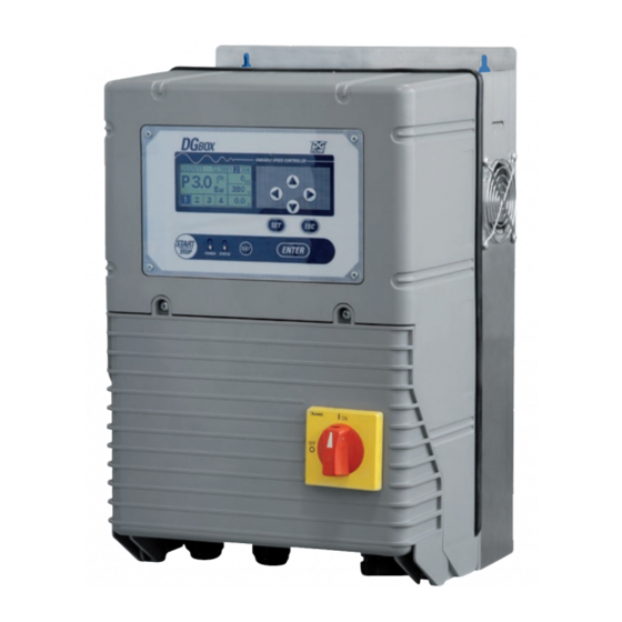
DGBOX
Inverter electronic control panels
for single pumps or pumping units
OPERATOR'S AND MAINTENANCE MANUAL
Model
DGB MV 30
DGB MV 55
DGB MV 75
DGB MVF 30
DGB MVF 55
DGB MVF 75
DGB MW 30
DGB SV 30
DGB SV 55
DGB SV 75
V in
V out
3 ~ 400V
3 ~ 400V
3 ~ 400V
3 ~ 400V
3 ~ 400V
3 ~ 400V
3 ~ 400V
3 ~ 400V
3 ~ 400V
3 ~ 400V
3 ~ 400V
3 ~ 400V
3 ~ 400V
3 ~ 400V
3 ~ 400V
3 ~ 400V
3 ~ 400V
3 ~ 400V
3 ~ 400V
3 ~ 400V
10154507A .03 - 170530
rev. 1602
A
P (kW)
8
3
14
5,5
18
7,5
8 + 8
3 + 3
14 + 14
5,5 + 5,5
18 + 18
7,5 + 7,5
8 + 8
3 + 3
8
3
14
5,5
18
7,5
EN
P (HP)
4
7,5
10
4 + 4
7,5 + 7,5
10 + 10
4 + 4
4
7,5
10
1
Advertisement
Table of Contents

Subscribe to Our Youtube Channel
Summary of Contents for DGFLOW DGB MV 30
- Page 1 OPERATOR’S AND MAINTENANCE MANUAL Model V in V out P (kW) P (HP) 3 ~ 400V 3 ~ 400V DGB MV 30 DGB MV 55 3 ~ 400V 3 ~ 400V DGB MV 75 3 ~ 400V 3 ~ 400V 3 ~ 400V...
- Page 2 INDEX PART 1 – QUICK INSTALLATION GUIDE SAFETY STANDARDS INSTALLATION POWER CONNECTIONS, PRESSURE AND FLOW SIGNAL CONNECTIONS INPUT / OUTPUT SIGNAL CONNECTIONS INPUT CONNECTIONS OUTPUT CONNECTIONS MASTER-SLAVE CONNECTIONS STARTING UP ACCESS TO MAIN MENU AND PARAMETER MENU SELF-LEARING CONFIGURATION MAIN MENU AND PARAMETER MENU SETTING THE PARAMETERS REQUIRED FOR OPERATION Setting the system pressure and the rated current Checking the direction of rotation of the motor...
-
Page 3: Safety Standards
SAFETY STANDARDS Safety important instructions. This symbol warns that failure to comply with the prescription leads to a risk of electric shocks. This symbol warns that failure to comply with the prescription leads to a risk of injury/damage to persons/objects. Before installation and use of the product, read this manual completely and thoroughly. -
Page 4: Description Of The Main Components
DESCRIPTION OF THE MAIN COMPONENTS PRESSURE SENSOR PRESSURE SENSOR FLOW SENSOR ( DANFOSS ) ( TEEVALVE ) 5 6 7 U V W GND R S T GND U V W GND PUMP 2 PUMP 1 LINE DANFOSS TEEVALVE 1. Disconnection switch 2. -
Page 5: Input / Output Signal Connections
INPUT / OUTPUT SIGNAL CONNECTIONS INPUT SIGNAL CONNECTIONS - permits connecting two input signals of the PRESS/FLOW 1 OUTPUT PRESS/FLOW 2 INPUT RS485 clean-contact type - see param. INPUT 1 CONFIG - see param. INPUT 2 CONFIG - If the contact of the sensor (eg. a level probe) is open, the operation is inhibited - Operating current is 5 mA for each input - Max capacity from Vdc is 100 mA. - Page 6 STARTING UP Before running, this Manual must have been carefully read and the instructions followed; wrong settings and operations are thus prevented that could cause operating faults. After performing the operations described in the INSTALLATION chapter, the inverter can be started. Before starting the system, the pumps must be primed (filling and air bleeding).
- Page 7 SELF-LEARNING CONFIGURATION DGBOX permits setting all the parameters required for self-learning: Startin g ..(O FF) To access WIZARD press ENTER within 5 seconds from DGBOX switch-on Press EN TER fo r WIZARD Select the WORKING PRESSURE using the arrows UP/DOWN and confirm by pressing ENTER W IZ A RD 1 /8...
- Page 8 MAIN MENU and PARAMETER MENU highlighted below the parameters that must be configured for the proper functioning of DGBOX (case referred to a single pump) Menu: BASE SETUP Par. Parameter code Description u.m. Default Min Step PRESSURE SET 1 Working pressure 1 PRESSURE SET 2 Working pressure 2 8-14-18 1.0...
-
Page 9: Menu: Maintenance
3.10 PRESSURE SENSOR Set up of connected pressure sensors 3.11 P SENSOR 1 F.S. Pressure sensor n°1 range 0-10 3.12 P SENSOR 2 F.S. Pressure sensor n°2 range 0-10 3.13 FLOW SENSOR Set up of connected flow sensors 3.14 UNLOCK SYSTEM Unlock function 3.15 VOLTAGE Main voltage... - Page 10 CHECKING THE DIRECTION OF ROTATION OF THE MOTOR (PUMP 1 ROTATION) For surface pumps (see fig. below): switch the system to TEST mode, start it by pressing START, and look to see whether the motor fan is turning in the direction indicated on the pump body. Stop the system by pressing STOP.
- Page 11 CHECKING THE FREQUENCY OF ELECTRIC MOTOR (MOTOR FREQ – default 50 Hz) Verify that the parameter MOTOR FREQ match the frequency of the motor plate (default 50 Hz) PARAMETER SYMBOL SHORT DESCRIPTION UNIT default min step MOTOR FREQ Motor frequency CHECKING THE MAXIMUM OPERATING FREQUENCY (MAX FREQ - default 50 Hz) Verify that the parameter MAX FREQ match the frequency of the motor plate (default 50 Hz) IMPORTANT: the choice of exceeding the maximum frequency is the responsibility of the installer,...
- Page 12 CONTROL OF DRY RUNNING APPLICATIONS WITHOUT FLOW SENSOR, with one or more pumps, submersible or surface In the presence of the flow sensor, dry running is automatically detected from the inverter, which gives a DRY RUNNING alarm. In the absence of flow sensor, to detect dry running it is necessary to properly set the parameters listed below.
- Page 13 TEST permits performing a FUNCTIONAL TEST of the pumps, both the variable-speed pump and the fixed-speed pump - It is automatically interrupted if not operations are performed from the keyboard for over 60 seconds; DGBOX automatically returns to OUT OF SERVICE mode. - To access the TEST mode, put the DGBOX in OUT OF SERVICE mode and then press the TEST key (see fig.
- Page 14 ALARMS DGBOX performs continuous checks of the electrical and operating parameters, thus ensuring the protection of the pump and the inverter itself from all types of common faults. It also distinguishes between slight and serious faults and acts accordingly, by either stopping the pump or not, emitting a luminous signal and showing a message on the display screen. OVERCURRENT: excessive current absorption, referred to the set value in parameter “PUMP x CURRENT”.
-
Page 15: General Remarks
PART 2 – USER’S MANUAL GENERAL REMARKS DGBOX is a range of ELECTRONIC CONTROL PANELS for single pumps or pumping units. DGBOX is powered by three-phase 400 Va.c. (optional version 230 Va.c.) and drives motor pumps with three-phase 400 Va.c. (or 230 Va.c.) motors. •... -
Page 16: Control Panel
CONTROL PANEL This comprises a backlit graphic display screen, a membrane keyboard and two signal LEDs The POWER LED (8) is the red networking indicator light. The STATUS LED (9) is the green start-of-at-least-one-pump indicator light. 1. display 2. scrolling arrows ( UP / DOWN/ RIGHT / LEFT ) 3. -
Page 17: Dimensions And Weights
TECHNICAL DATA and WORKING LIMITS Power supply voltage Three-phase 400 Vac (Three-phase 230 Vac) Power supply frequency 50-60 Hz output voltage Three-phase 400 Vac (Three-phase 230 Vac) output fequency 70 Hz Enclosure IP54 Working position vertical Fire / explosion hazard DGBOX units are not suitable for use in environments with risk of explosion. - Page 18 MULTI-PUMPS SYSTEMS system: inverter model description 1 VARIABLE MV 30 speed pump MV 55 MV 75 1 VARIABLE MVF 30 speed pump MVF 55 MVF 75 1 FIXED speed pump 2 VARIABLE MW 30 speed pumps 2 VARIABLE MV 55 + SV 55 speed pumps MV 75 + SV 75 3 VARIABLE...
- Page 19 PRODUCT MODELS AND IDENTIFICATION CODES DGB MVF 75 Product family (DGBOX) Master / slave unit (M = master, S = slave) First pump - variable speed (V) Second pump – fixed speed (F) Power in kW x 10 (ex. 75 = 7,5 kW) Models MV and SV (1 variable speed pump) MV 30 MV 55...
-
Page 20: Surge Tank
Model MW ( 2 variable speed pumps ) MWF 30 model Maximum motor rated power (single pump) @ 400 Va.c. Maximum motor rated power (single pump) @230 V a.c. Maximum current (single pump) 400 +/- 10% (230 +/- 10%) Three-phase voltage input frequency 50- 60... -
Page 21: Operating Modes
OPERATING MODES DGBOX has five different OPERATING MODES: mode description To access and modify the working parameters; can also be performed during 1. CONFIGURATION operation of the system (system mode WORK), while for particular parameters editing is possible only mode OUT OF SERIVCE. For the manual testing of the pumps;... - Page 22 BASIC CONFIGURATION (BASE SETUP) PARAMETER SYMBOL SHORT DESCRIPTION UNIT default min max step 1.1 PRESSURE SET 1 P1 Working pressure 1 * the maximum set pressure depends from the connected pressure sensor full scale P1 is the MAIN operating pressure; the DGBOX control will drive the connected pumps to keep the system at the selected pressure.
-
Page 23: Advanced Configuration
EXAMPLE: modifying the parameter PUMP 1 CURRENT 04/11/2011 15:02 MA IN MENU BASE SETUP PRESSURE SET 1 P 4.0 BASE SETUP 3 6. 8 HZ PRESSURE SET 2 A DV SETUP 410 V HARDWA RE SETUP PUM P 1 CURRENT 4.0 Bar MA INTENANCE PUM P 1 ROTATION... - Page 24 PARAMETER SYMBOL SHORT DESCRIPTION UNIT default min max step 2.5 MIN DRY PRES Minimum working pressure The parameter configures the minimum pressure must always be achieved by the system within the time TD (TD see next parameter 2.5 DRY RUN TIME); is expressed as a percentage of the working pressure (P1), and if is not achieved within the time TD, it means that the system is DRY RUNNING.
- Page 25 PARAMETER SYMBOL SHORT DESCRIPTION UNIT default min Max step RESPONSE 2.14 Inverter reactivity factor FACTOR The reactivity factor indicates the DGBOX response velocity, to return to set pressure, compared to pressure variations in the plant due to linked-unit withdrawal. The values that can be selected go from 1 (slow reaction, suitable for large-inertia plants or with possible resonance phenomena) to 5 (very fast reaction, suitable in case of fast changes in system pressure).
- Page 26 The OFF FREQUENCY setting relates to each PRESSURE SET operating pressure, and so if PRESSURE SET 2 (see – parameter 1.2 PRESSURE SET 2) is also used, the OFF FREQUENCY 2 parameter will also have to be set. The OFF FREQUENCY setting is automatically changed every time the PRESSURE SET operating pressure is changed, and it is moved to the new frequency below which it is considered that there is no more flow request.
-
Page 27: Hardware Configuration
PARAMETER SYMBOL SHORT DESCRIPTION UNIT default min Max step 2.20 KP P.I.D control proportional coefficient 2.21 KI P.I.D control integrative coefficient IMPORTANT: THE PARAMETERS KI and KP ARE CRITICAL BECAUSE THEY CHANGE THE BEHAVIOUR OF THE INVERTER, AND WRONG SETTING CAN CAUSE SYSTEM MALFUNCTIONING The parameters KP and KI constantly define the operating frequency of the inverter-controlled pump, depending on the fluctuation of system pressure compared to the set pressure. - Page 28 PARAMETER SYMBOL SHORT DESCRIPTION UNIT default min max step 3.4 PUMP 4 CONFIG Pump 4 configuration The parameter makes it possible to set up the pump 4 connection. The assignable functions are: NO FUNCTION Pump 4 is disabled (factory setting) EXT.
- Page 29 PARAMETER SYMBOL SHORT DESCRIPTION UNIT default min max step Configuration of analogic input 2 ANALOG 2 CONFIG The analogue input 2 can be set up in 2 different modes: The input is set up to read an analogue signal from 4 to 20 mA 4-20 mA The input is set up to read an analogue signal from 0 to +10 Vdc 0-10 Vdc...
- Page 30 PARAMETER SYMBOL SHORT DESCRIPTION UNIT default min max step 3.14 UNLOCK SYSTEM Unlock function UNLOCK SYSTEM: the UNLOCK SYSTEM function prevents the blockage of the mechanical seal or other rotating pump parts, caused by long stoppage periods. If enabled (by setting the ULS parameter from 1 to 99 hours, with 1 h step), the function starts the pumps for 5 sec.
-
Page 31: Maintenance
1.3. MAINTENANCE (MAINTENANCE) The MAINTENANCE menu is to be used only by qualified and trained personnel, who knows the problems of the inverter control and specific DGBOX characteristics. The menu permits two types of jobs: a) Inspection and routing maintenance jobs b) Configuration of the critical parameters for inverter operation and reset operations PARAMETER SYMBOL SHORT DESCRIPTION... - Page 32 PARAMETER SYMBOL SHORT DESCRIPTION 4.3 WORKING TIME Operating statistical data of working pumps It allows displaying the operating time of the selected pump (pump 1 or pump 2) and the number of start- ups made. PARAMETER SYMBOL SHORT DESCRIPTION 4.4 SET DATE-TIME Date and time setting menu It permits displaying and changing the date and time.
- Page 33 SYSTEM 0 4 /1 1 /2 0 1 1 1 5 :0 2 0 4 /1 1 /2 0 1 1 1 5 :0 2 0 4 /1 1 /2 0 1 1 1 5 :0 2 P 4 .0 P 4 .0 P 4 .0 0 0 .
- Page 34 Example: 0.1 bar set pressure increase (see fig. below). 04/11/2011 15:02 04/11/2011 15:02 SET P.1 04/11/2011 15:02 ENTER P 4.1 P 4.0 P 4.0 8 HZ 5 HZ 410 V 410 V 4.0 Bar 4.1 Bar 4.1 Bar 2.8 A 2.9 A 1.0-9.0 OUT OF SERVICE...
- Page 35 5. UPDATE The UPDATE mode permits DGBOX maintenance or software update operations. By means of a standard USB memory, it is in fact possible: to download the error message history records to download the set configuration to transfer it to other analogous DGBOX applications to update the FIRMWARE currently loaded on the power and control boards with others of more recent issue.
- Page 36 WRITE FLASH:049230/266110 !DO NOT DISCONNECTED POWER WRITE FLASH: OK EXTRACT USB KEY ! Press Enter For RESTART ENTER DGFLOW DGBOX STARTING...5 SN:DB1112000 FW:1.15 Example 2: download the error message record history onto the inserted USB memory; at the end of the procedure, the system returns to the initial display page of the UPDATE mode.
- Page 37 If DGBOX was in OFF condition at last switch-off, after initialisation and the starting phase, the system switches to OUT OF SERVICE mode (see fig. below). SYSTEM 0 4 /1 1 /2 0 1 1 1 5 :0 2 DGFLOW P 0 .0 DGBOX DGFLOW 3 .5 Bar 5 sec...
-
Page 38: Troubleshooting
- check the setting of the ammeter cutout of the variable- speed pump has tripped speed pump - the power board is out of order - Contact DGFLOW service for assistance P SENSE No pressure signal or out of scale - Check the pressure sensor connections to PRESS/FLOW... - Page 39 Message Cause intervention EXT OFF The inverter is out of service by means of Check the external signal external signal OVER Inverter module overheating - Make sure the air cooling channels are free and that the fans TEMP MOD are working - check the ambient temperature (max 45°C) - check the maximum operating current OVER...
-
Page 40: Warranty
Dangerous substances in electronic appliances (WEEE) 2014/30/EU Electromagnetic Compatibility Directive (EMC): CEI EN 61800 Bigarello, 02/11/2015 DGFLOW S.r.l. President Stefano Concini DGFLOW srl Via Emilia, 5 – 46030 Bigarello (Mantova) Italy Tel. +39 0376 340922 – fax +39 0376 249525 info@dgflow.it – www.dgflow.it...
Need help?
Do you have a question about the DGB MV 30 and is the answer not in the manual?
Questions and answers