Table of Contents
Advertisement
Advertisement
Table of Contents

Related Manuals for Murr Elektronik TREE M-4TX

Summary of Contents for Murr Elektronik TREE M-4TX
- Page 1 Introduction For your safety Product description Description of functions Technical data Mounting Electrical installation Start-up Configuration/settings Switch management ENGLISH MANUAL for TREE-managed switches Art. No. 58185 | 58186...
- Page 2 Falkenstraße 3 71570 Oppenweiler GERMANY Fon +49 (0) 7191 47-0 Fax +49 (0) 7191 47-491000 info@murrelektronik.com This document applies to IP20 devices of the “TREE-managed PROFINET switches” series Material short text Art. no. TREE M-4TX PN 58185 TREE M-6TX PN 58186...
-
Page 3: Table Of Contents
3.3 Structure of the conformance classes Description of functions 4.1 Basic functions 4.2 Additional functions Technical data 5.1 TREE M-4TX PN Art. no. 58185 5.2 TREE M-6TX PN Art. no. 58186 Mounting 6.1 Requirements 6.2 Dimensions 6.3 Installation of mounting rail 6.4 Fitting the device... - Page 4 9.1 Configuration 9.2 Web-based configuration 9.3 Configuration using the serial interface (CLI) 9.4 ID of the switch in the network Switch management 10.1 Simple Network Management Protocol (SNMP) Web server 11.1 Basics 11.2 INFORMATION menu 11.3 PROFINET menu 11.4 DEVICE CONFIGURATION menu 11.5 PORTS menu 11.6 NETWORK menu 11.7 SOFTWARE menu...
-
Page 5: Introduction
Introduction Introduction Symbols This document includes information and notes that have to be observed for your own safety and to avoid injuries and material damage. They are marked as follows: DANGER! Immediate danger Failure to observe this warning involves an imminent risk of death or seri- ... -
Page 6: Service And Support
Introduction Service and support Service and support Sales Our sales staff in-house and in the field, and our technicians will support you at all times. Sales support Our sales support will assist you: with consultation during the development phase of your application, ... -
Page 7: General Notes
Introduction General notes 1.3.1 Purpose of this document Purpose of this docu- This document describes the use of the Art. no. 58185 and 58186. ment It instructs the technical staff of the machine manufacturer or machine opera- tor on the installation, parameterization, electrical installation, commissioning as well as operation of the Art. - Page 8 Introduction 1.3.4 Storage and transport Storage and transport Avoid mechanical shocks during transport. Adhere to the prescribed climatic conditions (see chapter Technical Da- ta). 1.3.5 Environmentally friendly disposal Comply with Always dispose of scrap devices in compliance with the valid country-specific country-specific regulations for waste disposal waste disposal regula-...
-
Page 9: For Your Safety
For your safety For your safety Safety for you and peo- Read this chapter carefully. ple around you! Only then can you work with the device. General safety instructions The five safety rules Protect against high electrical voltage Disconnect Secure against switching on again Make sure that there is no voltage on all poles. - Page 10 For your safety SELV or PELV power supply unit WARNING! Life-threatening voltages! If there is a defect in a power supply unit, voltages on touchable components may reach 120 V DC or 50 V AC and more. Use only a power supply unit which allows max. 60 V DC or 25 V AC in case of error.
-
Page 11: Intended Purpose
For your safety Intended purpose Intended use The device has been designed and manufactured for: network connections between widespread network segments, industrial use, operation according to specified ambient conditions, installation in a switch cabinet. Foreseeable misuse Avoid misuse! ... -
Page 12: Emc Installation Guidelines
For your safety EMC installation guidelines Industrial use The device is manufactured according to the current state-of-the-art stan- dards. Both the robust mechanical construction and the design of the electron- ic components make it ideal for industrial use. To guarantee trouble-free operation, observe the following rules when install- ing the devices in systems. -
Page 13: Legal Regulations
For your safety Legal regulations 2.8.1 National/international legal regulations Murrelektronik GmbH herewith declares that the products and systems comply with the basic requirements and directives: 2014/30/EU Electromagnetic compatibility 2011/65/EU RoHS Warranty and liability claims Warranty and liability Warranty and liability claims shall be lost if claims ... -
Page 14: Product Description
4x10/100BT IP20 plastic RJ45 TREE M-6TX PN 58186 PROFINET-managed switch 6x10/100BT IP20 plastic RJ45 Product designation The designation is based on a scheme that indicates the product's function. format TREE M-4TX PN IP20 TREE Product family Function Managed Unmanaged Number of ports for twisted pair cables ... -
Page 15: Device Design
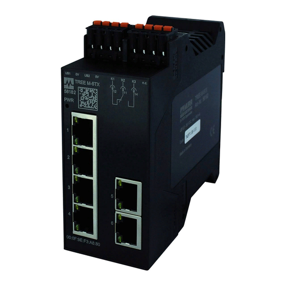
Class B and complies with the requirements of the Net- load Class 1. Fig. 3-1: TREE-managed PROFINET switch Art. no. 58185 and 58186 TREE M-4TX PN, Art. no. 58185 (on the left) TREE M-6TX PN, Art. no. 58186 (on the right) User manual 58185_TREE M4/6-TX PN IP20_hdb_en_10... - Page 16 Product description Benefits Easy configuration via PROFINET configuration tools. Optimum adaptation to the application thanks to variable equipment of the TX ports. Simplified network expansion and configuration. Automatic detection of data transfer rates at the RJ45 ports (10/100 Mbits/ ...
- Page 17 Port 1: standard mode (MDI mode (auto MDIX) All other ports in crossover mode (MDIX) USB interface The TREE M-4TX PN and TREE M-6TX PN TREE managed switches have a USB interface (serial - FTDI Virtual COM Port). Configuration: ...
- Page 18 Product description 3.1.3 Display elements Power on display (PWR) LED display The PWR power LED is located above the Ethernet ports. The PWR LED in- dicates the status of the two power supplies. Both power supplies are discon- nected. LED display LED status Description Green...
-
Page 19: Profinet Io Communication
Product description 3.1.4 Power supply Power supply An integrated supply unit regulates the voltage required for the device. The ex- ternal 24 V DC power supply is connected to the device using the four-pole connector. The device has an integrated reverse polarity protection system. 3.1.5 Alarm contact on TREE M-6TX PN TREE M-6TX PN contains an alarm contact (see Fig. - Page 20 Product description Fig. 3-6: Structure of the conformance classes CC-A CC-A offers basic functions for PROFINET IO with RT communication. Typical cycle time starting at 2 ms. In this case, unmanaged switches can be used, too. Wireless communication is possible only in this class. All TREE-managed PROFINET switch devices conform with this class.
-
Page 21: Description Of Functions
Description of functions Description of functions This section covers the basic functions of the switch. Detailed information about the management functions is available in Section 10 "Switch management". Basic functions 4.1.1 Protocol Settings Settings per port: Transfer rate Auto-Negotiation Settings for all ports: ... - Page 22 Description of functions 4.1.2 Media Access Controller (MAC) IEEE- 802.3 functions Each Ethernet port has a separate MAC that is capable of performing every function required under IEEE- 802.3, e.g., frame formatting, frame stripping, CRC checking, CSMA/CD enforcement, collision handling. Monitoring of incoming The Media Access Controllers check the validity of all received packets.
- Page 23 Description of functions 4.1.3 Frame switching Store-and-forward The switch operates using store-and-forward mode. mode The switch analyzes the source and destination whenever it receives a data packet. The switch can store up to 1024 MAC addresses in its address table, with a retention time of 330 seconds.
-
Page 24: Additional Functions
Description of functions Additional functions In addition to basic functions, the TREE-managed PROFINET switches have the following additional features: The Rapid Spanning Tree Protocol (RSTP) increases the operational and data transmission security through redundant network structures. The Media Redundancy Protocol (MRP) increases the operational and data transmission security through redundant network structures. - Page 25 Description of functions The spanning tree is generated on the basis of the following rules: Rules 1 | Selection of the root node (root device): Each network device is assigned a standardized identifier (ID) with a con- figurable priority number. The device with the lowest ID is the root device. If two devices have the same ID, the device with the lower MAC address is the root device.
- Page 26 Description of functions The following parameters can be adjusted when configuring the RSTP (see RSTP parameters Section 11.6 "NETWORK menu"): Hello Time: The time interval between each BPDU sent by the root device to provide information to the other network devices. ...
- Page 27 Description of functions 4.2.2 Operational and data transmission security thanks to MRP Fundamentals of Media Redundancy Protocol (MRP) is a redundancy protocol according to IEC 62439 for highly available networks. This deterministic protocol can be used to establish ring topologies. Reconfiguration times less than 200 ms are pos- sible.
- Page 28 Description of functions 4.2.3 Diagnostics The TREE-managed PROFINET switches support a large number of network diagnostic functions. (configuration see Section 9.2 "Web-based configuration"). Remote diagnostics Information on operating state and emergency situations Monitoring Monitoring of Ethernet connections and power supply PROFINET diagnostics Diagnostic messages to the PLC: ...
-
Page 29: Technical Data
Technical data Technical data TREE M-4TX PN Art. no. 58185 5.1.1 Electrical data Parameter Conditions Value Input voltage range 9.5 ... 31.5 V Nominal value +24 V Max. power consumption 1.9 W 70 mA ±25 % Current consumption At 24 V DC and max. - Page 30 Technical data Parameter Conditions Value Quality of service (QoS) In accordance with IEEE 802.p Frame priority (tagged) Port mirroring Status 5.1.4 Interfaces Supply Parameter Conditions Value Inputs Connector for power supply FKCT 2.5/4-ST BK Diameter of the Rigid/flexible, 0.2 ... 2.5mm connecting cables AWG 24 ...
- Page 31 Technical data 5.1.6 Environmental characteristics Climatic conditions Parameters Conditions Value Operating temperature 0 … +60 °C range Storage temperature range -40 … +85 °C Air humidity Non-condensing 5 ... 95 % (Operation and storage) ≤3000 m Operating altitude Above mean sea level NOTE Temperature rating of the cable to be connected to the field wiring terminals: ≤60 °C...
- Page 32 Technical data Immunity Parameters Conditions Value IEC 61000-4-2 4 kV / 8 kV Criterion A Radiated HF IEC 61000-4-3 10 V/m (80 MHz ... 1 GHz), Criterion A 3 V/m (1,4 GHz ... 2 GHz), 1 V/m (2 GHz ... 2.7 GHz) Burst on 24 V DC power IEC 61000-4-4 2 kV...
-
Page 33: Tree M-6Tx Pn Art. No. 58186
Technical data 5.1.8 Conformity, approval, certification Parameters Conditions Value Conformity with EU directive 2014/30/EU Certification according to UL UL standard 61010 E201820 PROFINET IO Device Conformance class B Netload class 1 Hazardous substance 有害物質 Part Name Lead Mercury Cadmi- Hexavalent Polybrominated bi- Polybrominated diphe- (Pb) - Page 34 Technical data Parameters Conditions Value ≤2 A Current strength ≤60 W Switching capacity Connector FKCT 2.5/4-ST BK 5.2.2 Ethernet functionality Parameters Conditions Value Ports Functionality According to IEEE 802.3 (Fast) Ethernet switch Transfer rate Automatic 10 Mbit/s 100 Mbit/s Duplex Automatic Port 2 to 6: Full- or half-duplex...
- Page 35 Technical data Parameter Conditions Value Connector for power supply FKCT 2.5/4-ST BK Diameter of the Rigid/flexible, 0.2 ... 2.5mm connecting cables AWG 24 ... 12 Ethernet interfaces Parameters Conditions Value Connection RJ45 jack shielded Connecting cable CAT5 100 Ω Impedance of connection line Cable length ≤100 m...
- Page 36 Technical data 5.2.5 Mechanical data Parameter Conditions Value Housing material Polyamide PA 6.6 Flammability class UL94 Dimensions L x W x D 111 x 45 x 99 mm Weight 170 g Fastening According to DIN EN 60715 Mounting rail TH35 Installation position Perpendicular to mounting rail...
- Page 37 Technical data Electromagnetic compatibility (EMC) Parameters Conditions Value Conducted emission EN 55022 / 24 V DC power sup- EN 55011, 150 kHz to 30 MHz Section 5 Class A (Industrial) Radiated emission EN 55022 / EN 55011, 30 MHz to 1000 MHz Section 6 Class A (Industrial)
- Page 38 Technical data 5.2.8 Conformity, approval, certification Parameters Conditions Value Conformity with EU directive 2014/30/EU Certification according to UL UL standard 61010 E201820 PROFINET IO Device Conformance class B Netload class 1 Hazardous substance 有害物質 Part Name Lead Mercury Cadmi- Hexavalent Polybrominated bi- Polybrominated diphe- (Pb)
-
Page 39: Mounting
Enough space for easy replacement of devices and for the connection of the connectors Diagnostic LEDs of the device are visible when in operation Dimensions 99 mm (3.90 in) TREE M-4TX PN TREE M-6TX PN 22,5 mm 45,3 mm 0.886 in 1.784 in... -
Page 40: Installation Of Mounting Rail
Mounting Installation of mounting rail Secure installation on mounting rail in accordance with DIN EN 60715: Observe the maximum permissible load-bearing capacity of the mounting rail. Always use clean, rust-free mounting rails to avoid contact problems. Fig. 6-1: TH 35 mm x 7.5 and TH 35 mm x 15 mm Make sure that heat can dissipate properly from the devices. -
Page 41: Removing The Device
Mounting Removing the device Removal from the Removing the cables mounting rail First remove the electricity cables. Removing the brackets Remove any brackets that have been fitted. Disconnecting multiple devices from one another If multiple devices are connected together, disconnect them from each other as you go along the mounting rail. -
Page 42: Electrical Installation
SELV : 0 V Fig. 7-1: Power supply Connecting the power supply to the TREE M-4TX PN Remove the insulation at the ends of the line to leave a length of 10 mm exposed. This will guarantee a secure contact. - Page 43 Electrical installation TREE M-6TX PN Power supply and alarm contact Art. no. 58186 UB1 : +24 V SELV : 0 V UB2 : +24 V SELV : 0 V Fig. 7-2: Power supply n.c. n.c. Fig. 7-3: Alarm contact Connecting the power supply and alarm contact to the TREE M-6TX PN Remove the insulation at the ends of the line to leave a length of 10 mm exposed.
-
Page 44: Start-Up
Start-up Serial interface USB interface The TREE-managed switches TREE M-4TX PN and TREE M-6TX PN have a USB interface (serial - FTDI Virtual COMPort). NOTICE This interface may only be used under the guidance of the support staff of Mur- relektronik GmbH. -
Page 45: Configuration/Settings
Configuration/settings Configuration/settings Configuration Assigning the The IP address can be assigned in the following ways: IP address DHCP/BOOTP Web server (see 11 "Web server") Configuration via the serial interface, command line interface (CLI) (see 9.3 "Configuration using the serial interface (CLI)") Web-based configuration NOTE PROFINET configuration see 12 PROFINET, Seite 90. - Page 46 Configuration/settings Access The current version of the switch can be accessed over HTTP (port 80) or HTTPS (port 443). NOTE These options are currently unavailable: Deactivating HTTP Changing the ports from 80 or 443 Unencrypted access All data transferred between the browser and switch using the HTTP protocol over HTTP will be unencrypted.
-
Page 47: Configuration Using The Serial Interface (Cli)
Configuration/settings Configuration using the serial interface (CLI) You can use the command line interface (CLI) to enter text commands in order to control the software of the switch. You can use the CLI to configure the switch using the serial service interface. 9.3.1 Keys Navigation... - Page 48 Configuration/settings 9.3.2 Access and login The following interfaces can be used to access and log in to the CLI: Configuration: Serial interface (115200 baud, 8N1, no flow control, XTerm TTY) SSH: User can log in as administrator (user “admin” and default or own pass- word).
- Page 49 Configuration/settings 9.3.3 IP configuration Fig. 9-3: IP Configuration NOTE Refer to Section 9.3.1 "Keys" for information about navigation and function keys. Options under IP Parameter Assignment: Static BOOTP DHCP Changing parameters when selecting “Static” Press <Enter> to select Static. Enter a valid IP address into the IP Address field.
- Page 50 Configuration/settings 9.3.4 System configuration Fig. 9-4: System configuration NOTE Refer to Section 9.3.1 "Keys" for information about navigation and function keys. The following settings can be changed: Web server activated / deactivated: Press <Enter> to activate or deactivate the web server. Security tip Deactivating the web server makes it impossible for unauthorized parties to access the switch and make changes through the web server.
- Page 51 Configuration/settings 9.3.5 Software update Fig. 9-5: Software update NOTE Refer to Section 9.3.1 "Keys" for information about navigation and function keys. Installing software URL: Enter the URL (tftp, ftp, http) of the file that you want to install. Start download: Press <Enter>...
-
Page 52: Id Of The Switch In The Network
Configuration/settings ID of the switch in the network As-delivered state When delivered, the IP address of the switch includes the following data: IP address 192.168.100.2/24 IP address 192.168.100.2 / subnet mask 255.255.555.0 Configuring the switch It may be necessary to change the IP settings of a workstation computer in or- from the work computer der to use it to access the switch. -
Page 53: Switch Management
Switch management Switch management The management unit of the switch creates an IP node with its own IP and MAC address. This makes it possible to manage the switch over SNMP (Sim- ple Network Management Protocol) using the Ethernet connection. The man- agement information is stored on the switch in the management information base (MIB). - Page 54 Switch management Events The switch (agent) sends a trap to the SNMP manager to show that it has de- tected an event. The switch detects the following events: Trap Description ColdStart Bootup trap (sent as soon as the SNMP daemon is start- ed.) Link state Sent as soon as a connection changes its status.
- Page 55 Switch management Integrated MIB engine The switch has an integrated MIB engine. The engine manages the following Managing MIBs MIBs, whose relevant parts were implemented. MIB-II (RFC 1213) System Group Contains basic information about the device (e.g., description, uptime, etc.) ...
- Page 56 Switch management A GetRequest can be used to send this OID to the switch. The switch will re- spond with a GetResponse message containing the result. NOTE Some of the data in the MIB of the switch is read-only, some is readable and writable.
-
Page 57: Web Server
Web server Web server 11.1 Basics NOTE You must be logged in as an administrator to reconfigure the switch. The TREE-managed PROFINET switch series has its own web server which can be used to configure the switch using a standard browser. The web-based configuration options are described step by step in the follow- ing section. - Page 58 Web server MENU Sub-menu Page layout Messages Settings Syslogserver Destination address OPENVPN Client OpenVPN client configuration Status 11.1.1 Reboot device Fig. 11-1: Status line / REBOOT DEVICE The button for rebooting the device is on the bottom right of each page. NOTE Rebooting the device will discard any changes to configuration data that have not been saved!
-
Page 59: Information Menu
Web server 11.2 INFORMATION menu 11.2.1 General Fig. 11-2: INFORMATION > General 1. General device information (Connection) Connected to is displayed when there is an active network connection to the switch. Flash LEDs Identify switch Click the green Flash LEDs link. The LEDs of the corresponding switch will flash several times. - Page 60 Web server 2. Detailed device Information Service information This section provides detailed information about the switch that are particularly useful when it needs to be serviced. These are: Serial number: The serial number of the switch. Order number: The order number of the switch for replacement or follow- up orders.
- Page 61 Web server 3. Connection The IP address, the IP assignment, the subnet mask and the default gateway are shown here. Change IP address Connection configura- Click the pencil icon. tion This will take you to the IP address configuration window (see Section 11.4.2 "IP configuration").
- Page 62 Web server 11.2.2 Neighborhood The switch supports the Link Layer Discovery Protocol (LLDP). This menu item displays information based on LLDP. Fig. 11-3: INFORMATION > Neighborhood The following information is provided in the Neighborhood field. Object Description Device port The port on which the neighbor was found Chassis ID of the neighbor IP address IP address of the neighbor...
- Page 63 Web server 11.2.3 ARP table Fig. 11-4: INFORMATION > ARP table The ARP table menu item lists the MAC addresses that the switch has learned. Parameters Description MAC address MAC address Status Learned or Static Port The port number on which the MAC address was seen Tab.
-
Page 64: Profinet Menu
Web server 11.3 PROFINET menu Display of the AR mode The AR connection is shown in the menu line next to the word "PROFINET": in the menu disconnected connected Web view The website in the menu item PROFINET provides information on the PROFI- NET status and the MRP status. - Page 65 Web server This concerns the following values: All PROFINET configurations Device name (in the PROFINET network) Device name (SNMP object SNMPv2-MIB::sysName.0) Contact (SNMP object SNMPv2-MIB::sysContact.0) Location (SNMP object SNMPv2-MIB::sysLocation.0) MRP settings LLDP mode The following values are retained: Port modes ...
-
Page 66: Device Configuration Menu
Web server 11.4 DEVICE CONFIGURATION menu The pages under theDevice Configuration menu item provide information about the switch and basic configuration settings. Fig. 11-6: DEVICE CONFIGURATION > System description Fig. 11-7: DEVICE CONFIGURATION > General information The Device Information page provides detailed information about the switch. This is divided into: ... - Page 67 Web server 11.4.1 System description Fig. 11-8: DEVICE CONFIGURATION > System description Change general information of the switch The following can be changed if needed: Device name Device description Physical location Contact Saving settings Click APPLY.
- Page 68 Web server 11.4.2 IP configuration Fig. 11-9: DEVICE CONFIGURATION > IP configuration Making changes under the IP configuration menu item The following can be changed if needed: IP address Subnet mask Default gateway The following can be selected under IP assignment: ...
- Page 69 Web server 11.4.3 Manage configuration Fig. 11-10: DEVICE CONFIGURATION > Manage configuration NOTE The switch does not perform name resolution (DNS). Make sure that you enter the address as a numerical IP address without any leading spaces, etc. Under Configuration Management, you can permanently save the current con- figuration of the switch or perform a factory reset of the switch.
- Page 70 Web server NOTE The switch must be rebooted after loading the configuration from a server. Click Reboot. Storing the current configuration on a server Enter the following data in the relevant fields: Server IP address Username Password ...
- Page 71 Web server 11.4.4 Network Time Protocol (NTP) Fig. 11-11: DEVICE CONFIGURATOION > NTP settings Under this menu item, you can synchronize the system time with times provid- ed by NTP servers in the connected network. You can enter a maximum of 16 NTP servers. The switch can be used as a time server.
- Page 72 Web server Synchronizing the system time with server times Enter the IP address of a connected NTP server here. Click the plus icon (+). You can enter a maximum of 16 NTP servers. It can take a few minutes to synchronize the time with the time server. The syn- chronization status is shown in the status column.
- Page 73 Web server 11.4.5 Safety Keep your password You can change security settings (such as changing your password) on the safe! Security pages. Keep your password safe! Make a note of your passwords and keep them in a secure location. If you forget a user password ...
- Page 74 Web server This certificate ensures that only the desired switch is used for communication, the encryption type used for communication. NOTE Internal regulations already exist for certificates depending on the user. Discuss installing the root certificate with your IT department. Installing a root certifi- Installing a root certificate in the web browser cate...
-
Page 75: Ports Menu
Web server 11.5 PORTS menu The ports of the TREE-managed PROFINET switches can be configured indi- vidually. This section contains basic settings. 11.5.1 Port table Fig. 11-13: PORTS > Port table The port table provides an overview of existing ports and their status. You can configure the most important parameters of the ports here. - Page 76 Web server Changing the configuration of a port Click the combo box of the relevant entry. Saving settings Click APPLY. The latest changes will be saved. NOTE TREE M-6TX PN, art. no. 58186 Port 1 does not support the mode 10BASE-T half-duplex 10 Mbit/s. NOTE An error message will be shown if you try to deactivate the last port.
- Page 77 Web server 11.5.2 Port statistics Fig. 11-14: PORTS > Statistics Statistics can be displayed for each port individually. Display statistics Click on the tab for the desired port. The statistics for the port will be displayed. Clear statistics for all ports Click Clear Port Statistics.
- Page 78 Web server 11.5.3 Port mirroring Fig. 11-15: PORTS > Port mirroring Read data Port mirroring passively reads incoming (ingress) and outgoing (egress) data that passes through a selected port. You can use the PORTS > Port mirroring page to activate or deactivate ports for port mirroring and configure a destination port.
-
Page 79: Network Menu
Web server 11.6 NETWORK menu You can configure RSTP details under the menu item Network > RSTP con- figuration. 11.6.1 RSTP configuration Fig. 11-16: NETWORK > RSTP configuration Status overview The RSTP page provides a status overview in the left-hand table and the configuration of the switch on the right-hand side. - Page 80 Web server Saving settings Click APPLY. The latest changes will be saved. 11.6.2 RSTP ports Fig. 11-17: NETWORK > RSTP ports - State table The State table of the ports shows how each port is currently configured: Parameters Options Description Edge port true...
- Page 81 Web server Parameters Description Port-No. Number of the port RSTP state Activate/deactivate RSTP at this port. Auto edge port Activate/deactivate Auto Edge at this port. Admin edge port Specify whether this port acts as an edge port. ...
- Page 82 Web server 11.6.3 Simple Network Management Protocol (SNMP) The switch supports SNMP and can be used to configure it. Fig. 11-19: NETWORK > SNMP Configure SNMP Activate or deactivate the sending of traps in SNMP Trap using the option SNMP trap send configuration.
-
Page 83: Software Menu
Web server 11.7 SOFTWARE menu The switch has a modular design. Additional functions can be added using software plugins. Plugins can be managed under Plugin Management. 11.7.1 Overview of software plugins Fig. 11-20: SOFTWARE > Plugin overview Software plugins The Plugins menu provides an overview of the software plugins on the switch. The Tab. - Page 84 Web server Possible status texts The status texts have the following meaning: Text Meaning Active Function active/services started (if available) Inactive Function disabled Tab. 11-12: Meaning of status icons More detailed information about additional functions is available from the sales team of Murrelektronik GmbH (see 1.2 "Service and support").
- Page 85 Web server 11.7.2 Install Fig. 11-21: Software > Install Installing software Installing plugins or new firmware Download so-called containers over HTTP or TFTP if necessary. Enter a source into the URL field. Select a file in the Image file field. Click Install.
-
Page 86: Log Menu
Web server 11.8 LOG menu 11.8.1 LOG > Log Fig. 11-22: LOG > Log How log messages are Display log messages displayed This section displays the latest log messages. The number of messages can be adjusted. Click the Entries combo box next to Messages. This will open the LOG >... - Page 87 Web server 11.8.2 LOG > Settings Fig. 11-23: LOG > Settings LOG > Settings Configuring the Syslog server You can configure up to 3 Syslog servers that can be reached in the net- work. The switch sends log messages to these servers. Saving settings ...
-
Page 88: Openvpn Menu
Web server 11.9 OPENVPN menu Fig. 11-24: OPENVPN > Client Switch as OPENVPN cli- The OpenVPN menu can be used to import a configuration file that will make the switch an OpenVPN client. An OpenVPN configuration file can be created with an OpenVPN server. - Page 89 Web server * Possible reasons for the OpenVPN server not being reachable Server not reachable A firewall is blocking the connection. The OpenVPN server is not ready to receive a connection. The time has not been set up on the client. The time must be the same on both the client and the server in order to open an OpenVPN connection.
-
Page 90: Profinet
PROFINET PROFINET General information The switch TREE-managed PROFINET switch is a PROFINET IO device. The switch complies with the requirements of Realtime Class 1, Conformance Class B and Security Level / Netload class 1. The data interval is 128 ms. The switch provides parameters, diagnostic and alarm functions which can be configured and evaluated by the PROFINET PLC. - Page 91 PROFINET AR operation Switching off/interrupting the AR operation If an AR connection is established, it cannot be switched off via the web server. An interruption is only possible by physically disconnecting the Ethernet con- nection. Disabled functions in the AR operation In the AR operation mode, many settings via the web server are no longer pos- sible, e.g.
- Page 92 Port link status Slot 1 - subslot 2 (byte 2 to byte 3 of slot 1) The 2 bytes consist of 16 bits. The bits in the switch TREE M-4TX PN have the following meaning: Meaning Port 1 Link down...
- Page 93 PROFINET Meaning Port 1 Link down Link up Port 2 Link down Link up Port 3 Link down Link up Port 4 Link down Link up Port 5 Link down Link up Port 6 Link down Link up 6 ... 15 Not connected;...
- Page 94 PROFINET Simplified device Once the switch TREE-managed PROFINET switch is configured via the change PROFINET PLC, a simplified device replacement is possible. If the device is replaced with a device of identical design (same article), the PROFINET PLC configures the new device automatically with the set parameters of the device to be replaced.
- Page 95 PROFINET PROFINET Factory Reset The second option is the PROFINET Factory Reset which resets all PROFI- NET-relevant configurations. The PROFINET Factory Reset can be carried out as described in: a | Chapter 11.3 "PROFINET menu", b | In the external diagnostic tool (e.g. PRONETA). The settings are reset to: Property Options...
- Page 96 PROFINET I&M data The I&D data can be read with the help of a configuration tool (e.g. Proneta or TIA portal). I&M 0 to 3 is supported. Status display in the The status is displayed in the web server (see Chapter 11.3 PROFINET web server menu, Seite 64 Display:...
-
Page 97: Operation
Operation Operation 13.1 Activation Boot process The firmware of the switch is automatically loaded when an external power supply is connected to the switch. The switch can be used as soon as the boot process is complete. LED display during the The LED display of the power supply will change from red to flashing green boot process during the boot process. -
Page 98: Maintenance And Cleaning
Maintenance and cleaning Maintenance and cleaning NOTICE Damage caused by defective or damaged devices! The functioning of the modules is not guaranteed. Replace defective or damaged devices. Clean the soiled contacts with oil-free compressed air or with alcohol and a leather cloth only. -
Page 99: Appendix
Appendix Appendix PRODUCTS AND ACCESSORIES You will find a wide range of products in our catalog or in our Murrelektronik online shop http://shop.murrelektronik.com 15.1 Glossary General terms: Term Meaning Intended purpose Use of a product, process, or feature according to the specifications, instructions, and information supplied by the MANUFACTURER. - Page 100 Appendix Term Meaning Auto-crossover A device switches between the channels while sending and receiving and stops when it receives connection data. Auto-negotiation Fast Ethernet configuration protocol. Devices on the network agree on a transmission mode that every device is capable of (100 Mbit/s or 10 Mbit/s; Full-Duplex or Half- Duplex) before data is actually transferred.
- Page 101 Appendix Term Meaning SNMP Simple Network Management Protocol Used to monitor devices in a network for states that require the attention of an administrator. STP, Spanning Tree Protocol A configuration protocol for bridges specified in the IEEE 802.1d standard. Different ports in the bridges are switched to stand-by in order to prevent data packets looping around the network in any structure containing bridges.
-
Page 102: Legal Notes
Legal notes Legal notes Disclaimer Murrelektronik GmbH has reviewed the contents of this technical documenta- tion for conformity with the described hardware and software. It is possible that certain details may not be correct. For this reason, we make no warranty re- garding the accuracy of this technical documentation, and assume no liability for any errors, in particular full conformity. - Page 103 Murrelektronik GmbH | Falkenstraße 3 | 71570 Oppenweiler | GERMANY +49 7191 47-0 | +49 7191 47-491 000 | info@murrelektronik.com www.murrelektronik.com The information in the manual has been compiled with utmost care. Liability for the correctness, completeness and topicality of the information is restricted to gross negligence.
Need help?
Do you have a question about the TREE M-4TX and is the answer not in the manual?
Questions and answers