Table of Contents
Advertisement
Quick Links
B843
Mounting and operating
instructions for
DRIESCHER
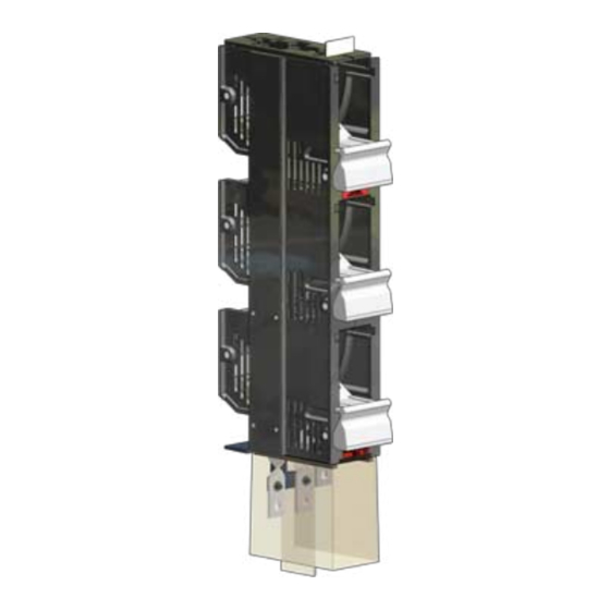
Low voltage -
fused-
switch disconnector
system 403
Rated current 400 up to 1445 A
ELEKTROTECHNISCHE WERKE
FRITZ DRIESCHER & SÖHNE GMBH
D-85366 MOOSBURG • PHONE +49 87 61 6 81-0 • FAX +49 87 61 68 11 37
http://www.driescher.de
infoservice@driescher.de
Advertisement
Table of Contents

Related Manuals for DRIESCHER B843

Summary of Contents for DRIESCHER B843
- Page 1 Low voltage - fused- switch disconnector system 403 Rated current 400 up to 1445 A ELEKTROTECHNISCHE WERKE FRITZ DRIESCHER & SÖHNE GMBH D-85366 MOOSBURG • PHONE +49 87 61 6 81-0 • FAX +49 87 61 68 11 37 http://www.driescher.de infoservice@driescher.de...
-
Page 2: Table Of Contents
Low voltage-fused-switch disconnector system 403 B843 Table of Contents 1 Introduction Notes on this manual ....... . - Page 3 Service address ......... . 6 Disposal CE marking The DRIESCHER low-voltage products are subject to the CE marking requirement in connec- tion with the Low Voltage Directive 2006/95/EC. The CE mark is applied to the individual packaging units.
-
Page 4: Introduction
Low voltage-fused-switch disconnector system 403 Introduction B843 Introduction Thank you for choosing one of our products. We hope it gives you many hours of successful and pro- blem-free operation. The low-voltage-fused switch disconnector system 403 has been specially designed and manufactu- red to meet your requirements. -
Page 5: Operating Conditions
Low voltage-fused-switch disconnector system 403 Product description B843 Product description 1.2.1 General The low voltage-fused-switch disconnector system 403 has been specially designed and manufactu- red to meet the requirements of our customers. They have been in trouble-free use for years. -
Page 6: Assemblies And Functional Elements 403
Low voltage-fused-switch disconnector system 403 Product description B843 1.2.4 Assemblies and functional elements 403 Connection above Connection lower Low voltage-fused-switch disconnector system 403 Pic. 1: , right cross section Low voltage-fused-switch disconnector system 403 Slider 1-pole Low-voltage high-rupturing-capacity fuse DIN 43620... -
Page 7: Operating Elements
Low voltage-fused-switch disconnector system 403 Product description B843 1.2.5 Operating elements Low voltage-fused-switch disconnector system 403 - 1-pole, 3-pole and 3-pole with operating handle switchable. Slider (B) with recessed grip above and down with inserted low-voltage high-rupturing- capacity fuse (C). -
Page 8: Safety
Low voltage-fused-switch disconnector system 403 Safety B843 Safety Intended use / guarantee The low voltage fused disconnector sysytem is intended for use under the conditions outlined in the section Technical data, on Page 16. Any use other than those outlined in this section is classed as an unintended use. -
Page 9: Dangers Caused By The Switching Device
Low voltage-fused-switch disconnector system 403 Safety B843 Dangers caused by the switching device The possible danger sources of the switching device are outlined below. Thorough introductory ses- sions and training for operators help minimise the danger to both people and equipment. -
Page 10: Assembly
Low voltage-fused-switch disconnector system 403 Assembly B843 Assembly Transport and storage of the low voltage-fused-switch disconnector system 403 For transport and assembly, only mount the low voltage-fused- Top side switch disconector system 403 from the outside, do not grip it into the system from the back, bottom or top. -
Page 11: Assembly On The Frame
Low voltage-fused-switch disconnector system 403 Assembly B843 Assembly on the frame Low voltage - fused-switch disconnector system type 403 / 400 A - 1445 A are mounted with 2 screws M8 on the frame. The busbars are supported by system 403. -
Page 12: Assembly On A Busbar
Low voltage-fused-switch disconnector system 403 Assembly B843 Assembly on a busbar (de-energized) For mounting necessary hexagonal nut, tension washer (Pic. 11) and detent edged ring must be attached on the connecting element fixed on the cardan-joint insert (see pic. 10), so that it can be accurately led while fixing on the connecting screw (M12). -
Page 13: Connecting The Switch Cables
Low voltage-fused-switch disconnector system 403 Initial commissioning B843 Connecting the switch cables Insert insulating baffle plate (K) into the appropriate fasteners (Pic. 14). The cables shall be laid over cable lugs or terminal in such a way that there is no mechanical stress(twisting, thrust, pressure, etc.) on the connecting bars (J). -
Page 14: Functional Check
Low voltage-fused-switch disconnector system 403 Initial commissioning B843 Functional check After the Low voltage-fused-switch disconnector system 403 is installed, the cables are connected and the insulating baffle plate (K) (see Pic. 14) is inserted, the flawless mechanical func- tion must be checked with a slider (B) without HRC fuse. - Page 15 Low voltage-fused-switch disconnector system 403 Operation B843 4.2.1 Commissioning Once the entire assembly and successful functional check are complete, the switching device is ready for use. 4.2.2 Operation Insert slider (B) with fuse (C) into the switchroom (H) . Slider is now in „Stand by position“. Press...
- Page 16 Low voltage-fused-switch disconnector system 403 Technical Data B843 Technical Data Low voltage-fused-switch disconnector system 403 Switch type audited according to VDE 0660/107 - IEC/EN 60947-1/-3) 400 A 630 A 910 A Rated operational current I Rated operational voltage U 400/500/690 V AC 400/500/690 V AC...
Need help?
Do you have a question about the B843 and is the answer not in the manual?
Questions and answers