Table of Contents
Advertisement
Advertisement
Table of Contents

Summary of Contents for Goodwe SECU-S Series
- Page 1 SECU-S HIGH VOLTAGE ESS User Manual Ver 1.0 2020-11-30...
- Page 2 • GOODWE makes no guarantees or warranties express or implied, concerning this document or any of the equipment and/or software it may describe, including but not limited to any implied warranties of utility, mer-chantability, or fitness for any particular purpose. All such representations or warranties are expressly dis-claimed. Neither GOODWE nor its distributors or...
-
Page 3: Table Of Contents
Contents 01 Safety Precautions ............... 1 Product Introduction ............2 2.1 Product Description ..................2 2.2 Symbol Definition ...................2 2.3 Introduction to System Components ............3 2.3.1 Introduction to SECU-S2.5 Battery ................. 3 2.3.2 Introduction to BCU-S0550 Control Box ..............4 03 Storage and Package ............6 3.1 Storage Environment ..................6 3.2 Packing Information ..................6 04 Installation of the System ............ 9 4.1 Installation Environment Requirement ............9 4.2 Installation Space Requirement ..............9 4.3 Installation of the System ................10 4.4 Electrical Connection . -
Page 4: Safety Precautions
All installation operations should be performed by trained and knowledgeable technical personnel who are familiar with local standards and electric systems. • Do not use the battery module if it is defective, broken, or damaged. • Do not attempt to disassemble, modify, or replace any part of the battery module without official authoriza-tion from GOODWE. • Damage to the battery module may lead to explosive electrolyte leakage. Please contact Technical Support for help immediately. • If electrolytes leak from battery modules, please avoid contact with the leaking liquid or gas. -
Page 5: Product Introduction
Product Introduction 2.1 Product Description The Energy Storage System consists of 5~8 SECU-S2.5 battery modules and 1 BCU-S0550 control box (hereinafter referred to as System). The System only works well together with GOODWE A-ES series in-verters. 2.2 Symbol Definition Symbol Definition Danger zone This indicates that the System must be grounded if extra grounding or equipotential bonding is required. Electrical voltage danger Explosion warning The battery contains corrosive electrolytes. Please avoid contact with leaked liquid or gas. Refer to all documentation provided with the System. Pay attention to safety protection during installation, operation, and maintenance. -
Page 6: Introduction To System Components
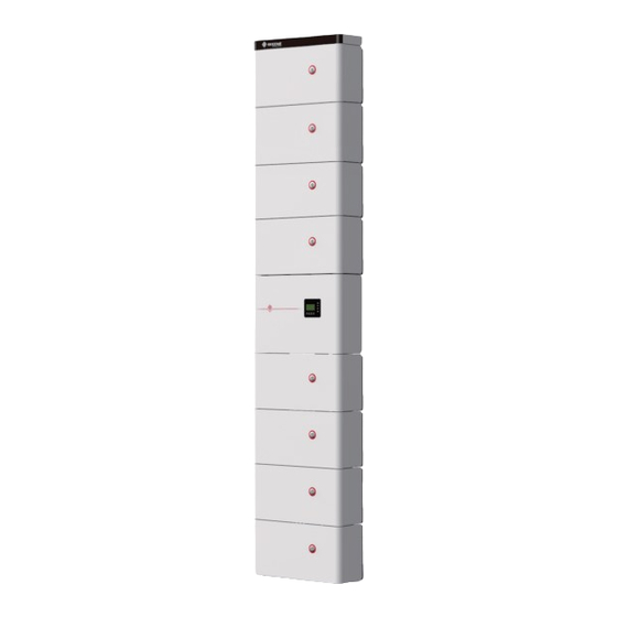
2.3 Introduction to System Components DESCRIPTION SECU-S2.5 Battery BCU-S0550 Control Box Cover of the System Install 4 SECU-S2.5 batteries under the control box and at most 4 SECU-S2.5 batteries over it, which means the system supports 8 SECU-S2.5 batteries maximum. This manual shows you the installation of 8 batteries. 2.3.1 Introduction to SECU-S2.5 Battery... -
Page 7: Introduction To Bcu-S0550 Control Box
SECU-S2.5 Ports Description BAT+ BAT- CAN COM Port(2 ports works the same) Dial Switch Indicator Indicator Status Indicator Status Green Light(on for 1s and then off for 1s) Normal Red Light Blinking(on for 1s and then off for 1s) Protecting Red and Green Light Blinking(red for 1s and then Faulty green for 1s) - Page 8 Description Description CAN COM Port LMU COM Port INV+ INV- BAT - BAT + Battery circuit breaker Indicator Buttons Display screen Ground point LMU COM Port CAN COM Port Definition Definition CANH CAN_H CANL CAN_L 1,2,3,6,7,8 RJ45 Registered Jack...
-
Page 9: Storage And Package
03 Storage and Package 3.1 Storage Environment If the equipment will not be installed or used immediately, please ensure that the storage environment meets the following requirements: • Pack the equipment with a packing box and put some desiccant in the box before sealing. • Keep suitable ambient temperature and humidity to avoid equipment damage. • Recommended storage temperature: -20℃~45℃(less than one month) or 0℃~35℃(less than one year). • Recommended storage humidity: 0%~75%RH. DO NOT install or operate the Syste if moisture penetrates. • Place the equipment in a cool place where away from direct sunlight. • Keep the equipment away from inflammable, explosive, and corrosive things. 3.2 Packing Information •... - Page 10 BCU-S0550 Control Box Box x1 Control box x1 Case x1 Wall hanging plate x1 Top Cover x1 M5*10 Screw x4 Accessory Box Buckle Wall hanging Power cable (BAT- accessories(PE Box x1 patch panel x1 Z-shape stand x2 bag included)x2 HV) x2 Power Communication Communication...
- Page 11 OT Terminal x4 Pin Terminal x5...
-
Page 12: Installation Of The System
04 Installation of the System 4.1 Installation Environment Requirement • Mount the System on a wall with sufficient load-bearing capacities such as a brick wall or concrete wall. If it is mounted on a wooden wall, evaluate its weight capability and the possibility of fall first. Meanwhile, the System must be grounding. -
Page 13: Installation Of The System
4.3 Installation of the System 1.Hold the battery handle to take it out from the packing box, and remove the protective case. 2.Hold the handle to separate the battery and the installation backboard. Keep the removed screws properly for future use. - Page 14 3.Perforate the mounting position with an impact drill (10mm diameter, 80mm depth) and clear the debris from the hole after drilling. Mounting hole distribution as follows. Mounting holes can follow either rectangular distribution(blue border) or dia-mond distribution(green border). 4.Install wall hanging plate •...
- Page 15 5.Put batteries inside the wall hanging plate and push them to the bottom to lock them togeth-er. 6.Attach the base plate to the battery.
- Page 16 7.Repeat step1~step6 to finish the second, third, and fourth batteries from bottom to top. 8.Take the control box out from the packing box as step 1 and step 2 showed. Keep the 4 re-moved M5*10 screws properly for future use. 9.Fix the female snap-lock(in the accessory box) on the control box. 3.5 N·M...
- Page 17 10.Directly fix the male snap lock on the decoration plate. 11.Perforate the mounting position with an impact drill (10mm diameter, 80mm depth) and clear the debris from the hole after drilling. Mounting hole distribution as follows. Mounting holes can follow either rectangular distribution(blue border) or dia-mond distribution(green border)
- Page 18 12.Install the wall hanging change-over stand on the wall hanging plate. 13.Fix the backboard of the control box.
-
Page 19: Electrical Connection
14.Install the control box. 15.Repeat step1~step6 to fi nish the fi fth, sixth, seventh, and eighth batteries from bottom to top. • There is a risk of injury when the battery is raised or lowered, or when it is fi xed to or removed from the wall stands since each battery weighs 37 KG (81.6 lbs). Raise the platform to ensure safety before installing the last 5-8 bat-tery modules. • The upper part of the battery module can only be wall-mounted, so the base plate is used for position only. Remove the base plate after positioning to re-duce stress on the control box. 4.4 Electrical Connection 4.4.1 Remove covers of the control box and batteries modules... -
Page 20: Install Pe Cables
4.4.2 Install PE cables • The internal ground cables are delivered with the battery system and con-nected in series. The two neighboring batteries are connected by ground points. • The external ground cables are not supplied. Cables with a sectional area big-ger than 10AWG are recommended. • Connect battery module PEC cables by M6 screws and an M6 OT terminal. Rec-ommended tightening torque is 5N.m. • Connect control box module ground cables by M5 screws and an M5 OT termi-nal. Recommended tightening torque is 3.5N.m. -
Page 21: Connect Power Cables
4.4.3 Connect power cables • Connect battery power cables in series, which means connect the anode of the battery to the cathode of the next battery. Connect power lines of the control box and batteries in parallel, which means connect the negative line of the bat-tery on the upside of the control box to its cathode while the positive line on the lower side to its anode. • Customers have to prepare cables used to connect the main control box and inverter. 6AWG copper core is recommended. • Confi rm that the switch of the control box is off . 1.Route the cable through the nylon tube, seal ring and waterproof joint, then crimp on OT ter- minals. • Ensure that the seal ring of the waterproof joint is properly 2.Connection fi gure placed in the plastic ring. -
Page 22: Connect Communication Cables
4.4.4 Connect Communication cables 1.Route the cable through the nylon tube, seal ring and waterproof joint, then crimp on the RJ45 terminal. 2.Connection fi gure • Remove the maintenance cover with a cross screwdriver before the connection. • Unscrew and remove the compression fi tting fi rst and screw it after routing the nylon tube. • Ensure that the seal ring of the waterproof joint is properly placed in the plastic ring. • Do not short-circuit the positive and negative terminals of the battery module when installing because there is no disconnecting switch in a single battery module. • Recommended torsion for tightening the compression fi tting is 7N.m. • Connect communication cables of all batteries and the communication box in sequence, except the control box and the fi rst battery under it. Then connect the bottom and the top battery module. 3.Seal the unused communication ports under the main control box by terminal resistances after connecting communication cables. -
Page 23: Dial Switch Settings
4.4.5 Dial Switch Settings • Diff erent dial switch values apply to diff erent battery modules. • After installing the battery, the dial switch inside it is inverted. Please pay at-tention to the specifi c setting value of the dial switch when setting it. 4.4.6 Cover of the System 1.Check the battery and the inverter, make sure that the power cable, communication cable, and PE cable inside the battery are connected correctly. 2.Set the dial switch properly. 3.Turn on the battery circuit breaker. - Page 24 4.Install the connection closure plate between the control box and the battery. • Please check the following details before turning on the battery circuit break: • The ground cable, power cable, and communication cable are connected cor-rectly and fi rmly. • The cable ties meet the cabling requirements and proper distribution. Also, the ties are tight and cut without sharp corners. • Place the battery in a reasonable space where is clean, tidy, and no construc-tion debris. 5.Install the cover of the battery system.
- Page 25 6.Install the top cover of the battery system. Appendix: quick drill paperboard (top) • Holes on the wall are equispaced(rectangular distribution) • Required plastic expansion screw torque: 10±10%N.m. • The fl oor must be horizontal when drilling holes in stacking way. • The paperboards have to be placed on the ground to avoid longitudinal skew. paperboard (bottom)...
-
Page 26: System Operation
05 System Operation 5.1 Check before power on To prevent damages to the battery system, please strictly follow the steps below: Take out the outer shell and the maintenance panel of the control box. Ensure the battery circuit breaker is OFF. Ensure all DC connections are ground and secured. Ensure all Communications Connections are ground. 5.2 Power on Push the handle to " ON " to turn on the battery circuit breaker. Confi rm that the battery system indicator is operating normally. 5.3 Function Description... -
Page 27: Setting The Parameters Of Secu-S On Pv Master App
Item Name Status Description Definition On: fault The battery Fault in normal or abnormal status Off: normal On: normal communication Communication Battery status between LCD and BMS Off: abnormal communication On: normal operation Current BMS Normal status Off: abnormal operation Item Object Description Backspace Exit from current interface or function. Move cursor up or increase value. Down Move cursor down or decrease value. Confirm selection. Power ( no 1st row PV power function) 2nd row Total (no function) PV generated energy 3rd row Battery... -
Page 28: Power Off
Select Battery on PV master: Select "SECU-S" on battery page in PV Master Application Select wrong battery will lead to BMS communication failure. 5.5 Power off To prevent damages to the battery system, please strictly follow the steps below: Take out the outer shell and the maintenance panel of the control box. Push the handle to " OFF " to turn off the Battery circuit breaker. Confirm that all LED lights are off. -
Page 29: Troubleshooting
06 Troubleshooting LCD Fault Fault Solution Display Turn off the system and wait for 2 hours. Cell temperature being Cell-Temp-Diff Then restart the system. If the fault persists, different please contact the service center. Module charge Restart the system. If the fault persists, please Chrg-Ov-Curr contact the service center. overcurrent Restart the system and switch off parts of the Module discharge over- Disch-Ov-Curr loads. If the fault persists, please contact the current service center. Turn off the system and wait for 2 hours. Pole-Ov-Temp Pole over-temperature Then restart the system. If the fault persists, please contact the service center. Restart the system. If the fault persists, please Cell-Ov-Volt Cell overvoltage contact the service center. Restart the system and switch it to discharge. Cell voltage being Cell-Volt-Diff If the fault persists 10 minutes later, please different contact the service center. Keep the battery in a place where the temperature is higher than -10℃ for more Cell discharge under low Disch-Low-Temp than 2 hours, then restart the system. If the... -
Page 30: Maintenance
07 Maintenance Maintenance Item Maintenance Period You need to fully charge the battery and discharge it to 30% if the Once Every 3~6 months battery is not in use. Check the wall hanging plate, fix it if it is not secured. Once Every 6 months Check whether the outer shell is broken, repair the painting, or Once Every 6 months contact the Aftersales Service Center if it is broken. Check the exposed cables, replace them, or contact the Aftersales Once Every 6 months Service Center if they are worn. Check whether there is debris accumulation around the battery to Once Every 6 months avoid affecting the battery heat dissipation. Check for water and pest to avoid prolonged intrusion. Once Every 6 months • Please contact after-sales for help if you find any problems that may influence the battery or the inverter. Disassemble without permission is strictly forbidden. • Please contact after-sales for help if the conductive wire is exposed. Do not touch or disassemble privately without permission. • In case of other emergencies, contact the after-sales as soon as possible. Please operate under the guidance of the after-sales personnel, or wait for them to operate. -
Page 31: Technical Parameters
08 Technical Parameters Technical Data SECU-S13 SECU-S15 SECU-S18 SECU-S20 Rated Energy* 12.80 kWh 15.36 kWh 17.92 kWh 20.48 kWh Usable Energy* 11.52 kWh 13.83 kWh 16.13 kWh 18.43 kWh Battery Module SECU-S2.5: 51.2V 50Ah 2.56kWh 37kg Number of Modules Cell Type LFP (LiFePO4) Cell Configuration 80S1P 96S1P 112S1P 128S1P Rated Voltage 256 V 307.2 V 358.4 V 409.6 V Operating Voltage 240~280 V 288~336 V 336~392 V 384~448 V Weight 200 kg 237 kg... -
Page 32: Limitation Of Liability
09 Limitation of Liability GOODWE will not be liable for any consequences like battery damage or property loss under the following circumstances: • Unauthorized modification, alteration, or parts replacement. • Change or erase the serial number privately. • Non-observance to the User Manual. • Improper use or misuse of the battery system. • Inadequate ventilation. • The maintenance routine does not follow accepted standards. • Force Majeure like earthquakes, storms, thunders, overvoltage, or fire hazards, etc. • Any external factors. - Page 33 StorageGo APP SEMS Portal APP SEMS Portal website LinkedIn Company's www.semsportal.com offical website JIANGSU GOODWE POWER SUPPLY TECHNOLOGY CO.,LTD No. 90 Zijin Rd., New District, Suzhou, 215011, China www.goodwe.com service@goodwe.com...
Need help?
Do you have a question about the SECU-S Series and is the answer not in the manual?
Questions and answers