Table of Contents
Advertisement
Quick Links
Advertisement
Table of Contents

Summary of Contents for FlexLink 5995512
- Page 1 5478EN-3 Spiral Elevator Type 5995512 User Manual Original Instructions 2011...
- Page 3 No part of this program and manual may be used, reproduced, stored or transmitted in any form or by any means without the written permission of FlexLink Components AB. The contents of this manual are for informational use only. All information and specifications contained in this document have been carefully checked to the best efforts of FlexLink Components AB, and are believed to be true and accurate as of time of publishing.
- Page 4 5478EN-3...
-
Page 5: Table Of Contents
Disposal ..........64 Unload the Spiral Elevator ...... 22 Reuse............64 Preparation..........22 Spare parts list........65 Unloading instructions ......23 Spiral Elevator 5995512......65 Mounting, installation, adjustment ..27 Supplier’s information......66 Provisions to be provided ...... 27 Manufacturer’s declaration......67 Page I of II... - Page 6 Page II of II 5478EN-3...
- Page 7 Preface Purpose of this manual The purpose of this manual is to describe various operations that are intended for the user to perform. This document contains remarks that point out a risky or specific situation to the user. In many cases this situation is provided with one of the symbols given below.
- Page 8 Requirements of the user The Spiral Elevator should only be operated by a person who has become acquainted with section 1 'safety' and trained in the use of the unit. The Spiral Elevator should only be installed by persons who have become acquainted with section 4 'unload the Spiral Elevator.
-
Page 9: Safety
System information The project number and/or general drawing number (identification number) shall always be specified when communicating with FlexLink with respect to the Spiral Elevator. The following detail plates are generally attached to the Spiral Elevator. -
Page 10: The Most Important Safety Conditions
Safety The most important safety conditions Before the Spiral Elevator is put in to service, the following safety conditions must be met: • Provide good ambient lighting. • Equipment users should have read and understood the operating instructions to operate, maintain or clean the machine. •... -
Page 11: Description Of Safety Provisions
Safety Description of safety provisions As a standard the Spiral Elevator is not provided with control or any safety provisions. Before putting the Spiral Elevator into service some safety provisions are to be incorporated. The purpose of these safety provisions is to protect the user, the product and the Spiral Elevator against undesired situations (damage). -
Page 12: Safety Measures To Be Taken
Safety Mechanical Remark Height / width Product entering the Spiral Elevator should not be of a size where the product detector can become jammed in the Spiral Elevator. In order to ensure that product cannot become jammed in the Spiral Elevator due to oversize some automatic checks for width and height can be done. -
Page 13: Explanation Of Symbols
Safety Explanation of symbols Pictogram symbols have been placed on the Spiral Elevator in order to identify to the user certain conditions or provide certain information on components of the Spiral Elevator. Description Picture 1.Spiral Elevator plate This contains the name and the address of the initial manufacturer, series or type indication, serial number and the... -
Page 14: Technical Specifications
Project System). Use of the Spiral Elevator outside of the scope detailed within the technical specification, quotation or documentation will invalidate the warranty. General FlexLink Spiral Elevator specification • 500 mm inclination per winding (9 degree) •... -
Page 15: Technical Data
Technical specifications Technical data 500 mm (inclination) 5000 mm (Max. heigth 8 windings) Lower height 600/700/800/900/1000 mm -50/+70 Machine incl. adjustable feet 5° 8x45° In/ Out Feed Configurations n159 1000 5478EN-3 Page 9 of 68... -
Page 16: Ordering Information
Example of a Spiral Elevator designation obtained from the FlexLink product configurator: Item no A D E F 5995512 100 - 1000 - 500 - S - A -TU - 800 - 3 - 25 5995512- Item number Chain width Spiral center of chain diameter... -
Page 17: Operating Conditions
Operating conditions The circumstances under which the Spiral Elevator can be operated partly depend on the materials selected. FlexLink has defined a number of parameters within which the Spiral Elevator would be allowed to function. Should the Spiral Elevator still be operated beyond these limiting values, FlexLink cannot guarantee the good functioning of the Spiral Elevator. -
Page 18: Introduction
FlexLink. • Insufficient or incorrect maintenance. FlexLink does not accept any liability for the consequential damage in case of failures of the machine, for example damage of products, interruption of operation, etc. Purpose of use The purpose of use of the Spiral Elevator is to transport products / goods in a vertical direction. -
Page 19: Description Of The Spiral Elevator
Introduction Description of the Spiral Elevator The Spiral Elevator is applied in a (transport) system where products can be transported vertically in a relatively small area. The Spiral Elevator can be coupled to other transport systems and be built according to the customer's needs. - Page 20 A or B. It is possible to have a configuration with which the output side is placed at a different angle. For any special configurations please contact FlexLink. Dimensions of the Spiral Elevator The height of the Spiral Elevator is dependant upon the low level height plus the number of turns of the spiral (see Technical Specification - Section 2 on page 8).
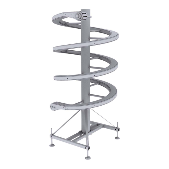
- Page 21 Introduction Components Spiral Elevator The Spiral Elevator consists of the following components: Figure 4 Components Spiral elevator 5478EN-3 Page 15 of 68...
- Page 22 The standard Spiral elevator is not delivered with a gear motor. However a gear motor may be added as part of the supply contract. Suggested Gear motor specifications can be obtained from the FlexLink Configurator or from FlexLink. The gear motor requires a Torque arm kit and a Absorber kit to prevent rotation and two types are available as follows: •...
- Page 23 Introduction General terminology used for the Spiral Elevator parts Central column Lower end unit Upper end unit Conveyor chain plate, Metal chain or link or slat transmission chain Bearing for conveyor chain Link Slide rail Conveyor Sprocket or Sprocket wheel Sprocket or Base frame Sprocket wheel...
- Page 24 Introduction 1) Conveyor plate 1) Motor 2) Basic chain 2) Drive shaft 3) Link 3) Sprocket wheel 4) Bearing 4) Torque arm Components conveyor chain Component Description Conveyor chain plate Narrow plastic plate provided with a guide roller. Conveyor plates are (slat) mounted in a row on the basic chain and so form the transport surface.
-
Page 25: Working Principle
Introduction Working principle The purpose of the Spiral Elevator is to transport products / goods vertically to bridge a difference of height. Figure 5 Principle sketch Spiral elevator Conveyor chain Upper end Lower end Return part Gear motor (not shown) 5478EN-3 Page 19 of 68... - Page 26 Introduction In most cases the Spiral Elevator is integrated in to a system. The input / output side of the Spiral Elevator is determined dependent on the system. In the following example, it is assumed that the input is at the lower end of the Spiral Elevator and that the product will bridge a difference in height in order to continue the required transport on the output.
-
Page 27: Control Units
Introduction Control units As a standard the Spiral Elevator is delivered without any control system. When a Spiral Elevator is supplied without control it is the responsibility of the system integrator / installer to design a suitable control system. It is preferable to install an isolating switch for the gear motor and it should be of a type able to be padlock off.With this switch the power to the gear motor can be switched / locked off in order to ensure safe working on the Spiral Elevator. -
Page 28: Unload The Spiral Elevator
Immediately after unpacking. Any damage must be detailed on the delivery note before signing for acceptance of delivery and also notified to FlexLink in order to possibly progress any warranty claim. Details of the dimensions and technical specifications are available on one or more of the following: •... -
Page 29: Unloading Instructions
Unload the Spiral Elevator Unloading instructions Initially the Spiral Elevator should be removed from the delivery vehicle by lifting the Spiral Elevator complete with any pallet base and / or packing materials. Before starting unloading, all fastening means (securing belts, screws, etc.) that secure the Spiral Elevator onto the transport vehicle must be removed. - Page 30 Unload the Spiral Elevator 4.2.1 Erecting the Spiral Elevator This section is for taller Spiral Elevators which are transported in the horizontal position. When putting the unit upright or when moving the Spiral Elevator make sure that the floor is level and clean and has sufficient load carrying capacity.
- Page 31 Unload the Spiral Elevator The following describes a typical method utilizing a hoist • The hoisting device is to be fastened to the cylinder at the top of the Spiral Elevator. Whilst hoisting, the hoist should be well fixed and must not be able to ride/shift away unexpectedly. •...
- Page 32 Unload the Spiral Elevator • Re-attach the frame with feet, to the final position at the bottom of the Spiral Elevator column. Attach the stay brackets between the Spiral Elevator column and the bottom frames. • Remove feet from the now horizontal position and re-fit in to the other holes in the frame to have the feet in the vertical position.
-
Page 33: Mounting, Installation, Adjustment
Mounting, installation, adjustment Mounting, installation, adjustment This section deals with the installation and adjustments for the Spiral Elevator. The safety conditions detailed in section 1.2 and the Safety Provisions detailed in section 1.3 should be read and understood before installation. Provisions to be provided Make sure before integrating that the safety measures detailed in section 1.4 are taken. - Page 34 Figure 7 Example of typical connection to an adjoining conveyor If conveyors are to be attached to the Spiral Elevator it is possible to use the specially designed joining pieces which are available from FlexLink. Page 28 of 68 5478EN-3...
-
Page 35: Assembly
Mounting, installation, adjustment Assembly This paragraph describes a number of operations for Spiral Elevators that are not delivered fully assembled. After having finished mounting the Spiral Elevator, the Spiral Elevator can be integrated (Section 1.4) in a system. 5.2.1 Motor The gear motor may be delivered separately with the Spiral Elevator and then has to be mounted on site. - Page 36 Mounting, installation, adjustment (Note: The conveyor and gear motor shown are not necessarily the same type as supplied.) • In the correct orientation, slide the gear motor on the shaft up till the locking ring (aligning the keyway to key). •...
- Page 37 Guide rail bracket Guide rail clamp support Guide rail clamp Guide rail Guide rail cover Distance piece Note! Grind or cut off the small lugs on the FlexLink guide rail bracket (or distance piece) before assembly. 5478EN-3 Page 31 of 68...
- Page 38 Figure 8 Connection mounting bracket If the guide rail is to be FlexLink polyethylene, XLRS 3x15 P type then to ensure rigidity at the ends it is suggested to pre-bend a 150 mm long and 10x10 mm metal bar or an Ø10 mm metal rod to the radius of the guide rail and insert it in the guide rail at each end.
-
Page 39: Validation
Mounting, installation, adjustment Validation Initially the validation checks should be for visual condition and dimensions. Subsequently a short test run should be made with the Spiral Elevator in an un-loaded condition. 5.3.1 Dimension check Spiral Elevator The technical specification and / or relevant drawing can be used for the dimension check. - Page 40 Mounting, installation, adjustment Test Procedure Test Checks Duration Carried out Run the Spiral Elevator Check the Spiral Elevator for the Yes / No for very short duration rotation direction of the conveyor (at 10 Hz if variable chain. If this is not correct, then make speed motor).
-
Page 41: Integration In A (Transport) System
Mounting, installation, adjustment Integration in a (transport) system The Spiral Elevator is a machine that is integrated in a system of conveyors. This means that an input and output are to be connected to it. If the Spiral Elevator is to be fitted into an existing situation, this usually gives more problems with the installation than in a completely new situation. - Page 42 Mounting, installation, adjustment 5.4.2 Checklist integration After the integration the checklist given below should be completed to ensure a satisfactory integration. Component Remark Checked Lower end Is the lower end at the correct height and is the distance to the Yes / No adjacent conveyor / machine satisfactory (should be below 25mm and suitable for other considerations regarding product...
-
Page 43: Setting Of The Spiral Elevator
Mounting, installation, adjustment Setting of the Spiral Elevator The mechanical and control setting for the Spiral Elevator need to be done correctly, with particular regard to the ends and transfers to ensure good operation. 5.5.1 Mechanical Mechanically there are a number of items which can be set for the Spiral Elevator. - Page 44 Mounting, installation, adjustment 5.5.2 Controls The table below gives some general guidelines with regard to the control system used to operate the Spiral Elevator. . Component Setting Remark Frequency control The speed difference of the feeding conveyor to the (where fitted) Spiral Elevator or the Spiral Elevator to the receiving conveyor should generally be below the setting value.
-
Page 45: Test Run - Partially Loaded
Mounting, installation, adjustment Test run - partially loaded In this paragraph the Spiral Elevator will be checked in a semi-loaded condition with all safety provisions activated. If during the test run any of the following situations occur, the test must be stopped and the Spiral Elevator must not be tested further until the issue has been solved. - Page 46 Mounting, installation, adjustment Check Remarks Passed Are any conveyor chain This may occur if there are some loose Yes / No plates moving unexpectedly conveyor plates (see Section 6.3 on page 57). at any position throughout the Spiral Elevator? Are there any conveyor chain This may occur because conveyor plates are Yes / No plates which are raised at...
- Page 47 Mounting, installation, adjustment Check Remarks Passed Is the product properly Generally the product will not twist whilst Yes / No transported throughout the travelling up or down the Spiral Elevator. If Spiral Elevator. undue twisting does occur, discuss this with the supplier.
- Page 48 Mounting, installation, adjustment Check (safety) provisions The basic Spiral Elevator supplied by FlexLink does not include any additional safety provisions such as isolators, stop/start devices, emergency stopping systems or guards at the in-feed / out-feed ends. Any issues with regard to the safety items should be investigated and discussed with the designer of the control and safety system.
-
Page 49: Technical Maintenance
Technical maintenance Technical maintenance Technical maintenance is an important part of this manual. Good maintenance will prolong the life of the Spiral Elevator and help to reduce any costs resulting from breakages or downtime. This section includes a troubleshooting list in section 6.3 and a maintenance schedule in section 6.4. - Page 50 Technical maintenance 6.1.2 Checking chain tension and chain stretch The conveyor chain of the Spiral Elevator must have the correct tension. If the tension is not correct, the following may occur: • Chain runs off the sprocket (jumps a cog). •...
- Page 51 Therefore the metal chain must be replaced when the measured distance is more than 271 mm [10,67"]. • Refer to section 8 for spare part numbers and contact FlexLink to procure the necessary parts. Nominal 267 mm, Maximum 271 mm Figure 11 Tape measure on conveyor chain Note! If more than 1.5% of the original number of conveyor chain...
- Page 52 Technical maintenance 6.1.3 Checking guide rail Products that are transported over the Spiral Elevator can make contact with the guide rail. A stoppage may damage the guide rail. This may later result in products getting stuck at the damaged place and therefore it is important that the guide rail is regularly checked for irregularities and is adjusted or repaired if necessary.
-
Page 53: Maintenance Procedures
Technical maintenance Maintenance procedures It's strongly recommended to perform maintenance activities according to the methods described. During maintenance proper and safe tools must be used. Before disassembling any part please refer to the assembly section in this manual. 6.2.1 To move the conveyor chain Follow the below procedure to move the conveyor chain within the Spiral Elevator: Ensure that the Spiral Elevator is free of products... - Page 54 Technical maintenance 6.2.2 Replacing conveyor plates(slats) This paragraph explains how to replace a broken or missing conveyor plate (slat). Note! If a conveyor plate is incorrectly mounted damage to the Spiral Elevator and the products transported on it may result. Danger: Make sure that the main switch has been switched off, and safely isolated.
- Page 55 Technical maintenance • Apply force on the middle of the slat so that it clicks onto the chain. You can possibly use a rubber mallet for this. Repeat this procedure if more than one slat needs to be placed. Figure 13 Placing a slat •...
- Page 56 If the conveyor chain stretch exceeds the limit (see Section 6.1.2 on page 44) the chain must be shortened. Shortening the chain can best be done at the lower end. FlexLink delivers a chain tensioner with the machine to assist in this procedure.
- Page 57 Technical maintenance 6.2.4 Align sprocket wheel If the conveyor chain does not run smoothly or is noisy, one of the sprocket wheels at the conveyor ends may not be aligned correctly. This may cause extra wear of chain and sprocket wheel. Tools Procedure to align sprocket wheel at lower or upper end •...
- Page 58 Technical maintenance 6.2.5 Replace sprocket wheel, upper end Find the conveyor plate with a coloured dot marked on it and move this conveyor plate to the upper end of the Spiral Elevator. Under this conveyor plate there is a locking link that can easily be removed. Tools Danger: Make sure that the main switch has been switched off, and safely isolated.
- Page 59 Technical maintenance • Once the gear motor has been removed, the grub screw in the locking rings of the bearing blocks can be loosened. The bearing blocks can then be removed and slid off of the ends of the shaft. •...
- Page 60 Technical maintenance 6.2.6 Replace sprocket wheel, lower end Find the conveyor plate with a coloured dot marked on it and move this conveyor plate to the lower end of the spiral conveyor. Under this conveyor plate there is a locking link that can easily be removed. Tools Danger: Make sure that the main switch has been switched off, and safely isolated...
- Page 61 Technical maintenance Note! The shaft and sprocket are removed as one piece. These can be replaced as one piece or as individual items. If replaced as individual items make note of the orientation of the sprocket wheel on the shaft. •...
- Page 62 Technical maintenance 6.2.7 Lubricate the motor The lubrication of the Spiral Elevator gear motor should lead to a continuous good functioning of the machine. The oil level of the motor is to be checked regularly. • For details of the oil type see the motor specification plate or the documentation from the supplier of the Spiral Elevator or the supplier of the gear motor.
-
Page 63: Troubleshooting List
Technical maintenance Troubleshooting list Trouble Possible cause Solution Spiral Elevator No power (volts) at the gear motor The cause for lack of does not work power to be investigated by qualified personnel. Gear motor defective Replace the motor Spiral Elevator Teeth on the sprocket wheel worn Replace the sprocket does not work, but... - Page 64 Spiral Elevator orientation. Defective transition roller arrangement Contact the supplier of (if fitted) the FlexLink Spiral Elevator. The product is pushed to the outside, The feed rate of the because there is no space between product is too high for the products on the Spiral Elevator.
- Page 65 Technical maintenance Trouble Possible cause Solution Transfer of product Product stoppage Repair the transfer unit on to or off of spiral if faulty elevator is poor (depending upon Product load too high Check the technical product & specification for the specification, the maximum product actual transfer may...
-
Page 66: Maintenance Schedule Spiral Elevator
Technical maintenance Maintenance schedule Spiral Elevator The FlexLink Spiral Elevator generally requires relatively little maintenance. The list below details the general maintenance operations which must be carried out at the normal time intervals for those maintenance operations. The maintenance intervals are for a Spiral Elevator operating in normal conditions with single shift working (8 hours per day) and in a normal environment. - Page 67 Technical maintenance Maintenance schedule Spiral Elevator Execution Interval Remark Clean conveyor Monthly Regular cleaning depends on product and environment Check the conveyor chain for Daily It is the task of the operator to broken or missing conveyor check this daily (see user’s plates, replace if necessary manual) Check the chain tension...
-
Page 68: Put Out Of Commission
Put out of commission Put out of commission Decommissioning should be undertaken in a safe and controlled manner. This section details the items which must be done for this decommissioning. Disconnect the power sources The main power isolator must be turned off and 'locked off' or power permanently removed from the isolator. -
Page 69: Transport
Put out of commission Transport While transporting the Spiral Elevator a number of safety measures are to be taken. Use the same tools and equipment as indicated in section 4 for the Unload of the Spiral Elevator. A suitable Method Statement and Risk Assessment for the dismantling and transportation should be done by the relevant responsible person. -
Page 70: Disposal
Clarification for the new application should be sought from the original Spiral Elevator supplier or FlexLink (there may be a charge for this service). A full Risk Assessment will need to be completed for the use in the new application before the Spiral Elevator can be put in to service. -
Page 71: Spare Parts List
Spare parts list Spare parts list Spiral Elevator 5995512 Item Description Part No Qty Comments Chain link 5112485 TPS1-MF-R PP Bearing 5112486 Kit of 20 pcs Connection link 5112487 3/4” steel, Kit of 5 pcs Sprocket wheel 5112488 3/4” 19T for shaft 30mm... -
Page 72: Supplier's Information
Supplier’s information Supplier’s information This document was drawn up by: FlexLink Components AB Date: 2010/08/23 Copyright: FlexLink Sweden, 2010 The machine was produced/ supplied by: Flexlink Components AB Tel: +46 (0)31-337 31 00 SE-415 50 Göteborg Fax: +46 (0)31-337 31 95 Sweden E-mail: info@flexlink.se... -
Page 73: Manufacturer's Declaration
Manufacturer’s declaration Manufacturer’s declaration The Spiral Elevator is supplied to be incorporated within an overall transport system and is not intended to be used as a stand alone piece of equipment. Therefore a Certificate of Incorporation is applicable for the unit. Any Certificate of Incorporation will be contained within the separate documentation supplied with the Spiral Elevator or overall system. - Page 74 Manufacturer’s declaration Page 68 of 68 5478EN-3...
Need help?
Do you have a question about the 5995512 and is the answer not in the manual?
Questions and answers