
Subscribe to Our Youtube Channel
Summary of Contents for Ametek Land 099.465
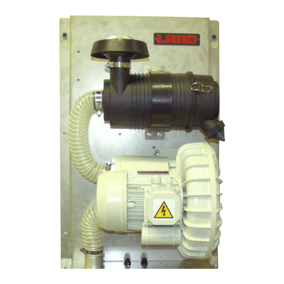
- Page 1 Plate Mounted Blower Unit User Guide Publication Nº 770-073 Language: English Issue 5 11 July 2013 © Land Instruments International, 2010-2013...
- Page 2 IMPORTANT INFORMATION - PLEASE READ Health and Safety Information Read all of the instructions in this booklet - including all the WARNINGS and CAUTIONS - before using this product. If there is any instruction which you do not understand. DO NOT USE THE PRODUCT. Safety Signs WARNING Indicates a potentially hazardous situation which, if not avoided, could result in death or...
- Page 3 Contact Us UK - Dronfield USA - Pittsburgh Land Instruments International AMETEK Land, Inc. Tel: +44 (0) 1246 417691 Tel: +1 412 826 4444 E-Mail: land.combustion@ametek.co.uk E-Mail: combsales@ametek.com Web: www.landinst.com Web: www.ametek-land.com For further details on all LAND/Ametek offices, distributors and representatives, please visit our websites.
-
Page 5: Table Of Contents
User Guide Plate Mounted Blower Unit Contents Blower Configurations Health and Safety Warnings Equipment Operation Power Supply Face and Eye Protection Protective Clothing Installation Description The Need for Air Purging Blower unit configuration Optional Items Description - Blower Options Installation Installation Guidelines Installation Mains Power Connection - High Capacity Blower... - Page 6 Plate Mounted Blower Unit User Guide...
-
Page 7: Blower Configurations
Blower Configurations IMPORTANT Blower Models covered by this Instruction Manual Part Power Mounting Capacity Voltage Frequency Number Consumption 099.465 Base Plate High 230V single phase 50 Hz 750 W 099.466 Base Plate High 110 V single phase 60 HZ 1100 W 099.467... -
Page 8: Health And Safety Warnings
Plate Mounted Blower Unit User Guide Health and Safety Warnings 2.1 Equipment Operation Use of this instrument in a manner not specified by LAND Combustion, may be hazardous. 2.2 Power Supply Ascertain that all power lines are isolated before carrying out any work on the electrical connections. -
Page 9: Description
User Guide Plate Mounted Blower Unit Description 3.1 The Need for Air Purging In order to ensure that the optical system remains clean, air must be supplied continuously through the purge unit. Though negative pressure within a stack may draw sufficient air through the air purge nozzle to prevent a build up of dust and fumes, a positive pressure air supply is recommended in all installations. -
Page 10: Optional Items
Plate Mounted Blower Unit User Guide 3.3 Optional Items The following items are available as options to the standard configuration with the blower unit. They are all customer fitted on-site. Description Part Nº Y-piece 704.340 Air Pre-filter 317.560 Pressure Switch Assembly and Pitot (0.5 to 5.0 mbar) 704.383 Pressure Switch Assembly and Pitot (5.0 to 20.0 mbar) 704.385... -
Page 11: Description - Blower Options
User Guide Plate Mounted Blower Unit 3.4 Description - Blower Options Y-piece This optional Y-piece adaptor is used where a single blow is capable of supplying sufficient air to both sides of the instrument. The adaptor splits the blower air supply output into two equal parts. - Page 12 Plate Mounted Blower Unit User Guide Weatherproof Cover The blower unit is environmentally rated to IP 55 / NEMA 4. Where further protection is required, up to IP 55 / NEMA 4X, then the optional Weatherproof cover should be used and fitted to the blower assembly. Weatherproof cover is customer fitted at site.
- Page 13 User Guide Plate Mounted Blower Unit Part Nº Description 704.340 Y-piece (optional) 317.603 Rain Cap 317.446 Differential Pressure Switch 317.447 Low Pressure Trip 704.374 Weather Proof Cover (Option not shown) 317.604 Safety Filter Element (optional) 317.561 Air Filter Element 318.517 Hose Clip 306.082 Air Hose (per yard)
-
Page 14: Installation
Plate Mounted Blower Unit User Guide Installation 4.1 Installation Guidelines Surface Temperatures Surface temperatures of the motor can reach 100 °C / 212 °F. If there is a possibility of the accidentally touching the motor surface in the intend- ed location, the weatherproof cover or some other guard must be fitted. Air Quality Use only in locations where the incoming air is not corrosive, inflammable or explosive. -
Page 15: Installation
User Guide Plate Mounted Blower Unit 4.2 Installation The mountings for the air blower should be marked out in the fixing position. Fit the plate mounted blower to the mounting position using suitable bolts. There are six holes available for attaching the baseplate to a flat, vertical surface. -
Page 16: Mains Power Connection - High Capacity Blower
Plate Mounted Blower Unit User Guide 4.3 Mains Power Connection - High Capacity Blower CAUTION Ensure mains power supply is isolated before making any connec- tions. Never remove the connector cover when the mains power is switched on. The blower unit requires a mains power supply to that stated on the blower rating plate. -
Page 17: Mains Power Connection - Low Capacity Blower
User Guide Plate Mounted Blower Unit 4.4 Mains Power Connection - Low Capacity Blower CAUTION Ensure mains power supply is isolated before making any connec- tions. Never remove the connector cover while the mains power is switched on. The blower unit requires a mains power supply to that stated on the blower rating plate. -
Page 18: How To Fit A Pressure Switch
Plate Mounted Blower Unit User Guide How to fit a Pressure Switch This Pressure Switch is a customer fitted option The pressure switch assembly is supplied in two parts: • Pressure Switch, fitted with two rubber pipes, and mounting plate (not shown) •... -
Page 19: How To Fit A Y-Piece Adaptor
User Guide Plate Mounted Blower Unit How to fit a Y-Piece Adaptor The blower unit is dispatched with a single hose adaptor fitted. Where the blower is being used to supply two instruments a ‘Y’-piece adaptor should be fitted. Fitting Procedure Push the ‘Y’... -
Page 20: How To Fit An Air Pre-Filter
Plate Mounted Blower Unit User Guide How to fit an Air Pre-filter Where the ambient air quality around the blower unit contains high levels of dust or ash, then it is recommended to fit an air pre-filter. Fitting Procedure It is necessary to remove the rain cap before fitting the pre-filter. Loosen the clip connector around the rain cap and pull upwards until the cap is free. -
Page 21: How To Fit A Safety Filter
User Guide Plate Mounted Blower Unit How to fit a Safety Filter The Safety Filter (Part No. 317.604) is an optional item. It provides protection against dust ingress, if the air filter fails. Fitting Procedure Unclip and remove the black filter cap. Remove the air filter. -
Page 22: How To Fit A Weatherproof Cover
Plate Mounted Blower Unit User Guide How to fit a Weatherproof Cover The weatherproof cover should be fitted when the location of the blower would subject it to extreme weather conditions. Fitting Procedure Hook the top of the cover into the grooves in the top of the baseplate (Step Allow the bottom of the cover to swing down into position. -
Page 23: Specifications
User Guide Plate Mounted Blower Unit 10 Specifications Supply voltages and frequency are indicated on the blower rating plate. Voltage Frequency Power Recommended Circuit Consumption Breaker (type C) 230 V single phase AC 50 Hz 750 W 10 A 110 V single phase AC 60 Hz 1100 W 220 V single phase AC... -
Page 24: Maintenance
Plate Mounted Blower Unit User Guide 11 Maintenance The Plate-mounted blower unit has been designed for a minimal amount of routine maintenance. It is important to follow the recommended schedule. This schedule should be run alongside that recommended for the instrument itself. Maintenance Schedule Item Part... - Page 25 User Guide Plate Mounted Blower Unit Replacing an Air Filter All blowers have a filter fitted as standard. The filter cartridge is easily accessible within the filter housing and must be cleaned or renewed at regular intervals. Refer to Maintenance schedule. Fitting Procedure Unclip and remove the cover.
-
Page 26: Consumables And Spare Parts
Plate Mounted Blower Unit User Guide 12 Consumables and Spare Parts The following spare parts are available for the range of blowers. Description Part Nº (required if only 1 blower is used) 704.340 Y-piece Rain Cap 317.603 Air Pre-filter 317.560 Pressure Switch Assembly and Pitot (0.5 to 5.0 mbar) 704.383 Pressure Switch Assembly and Pitot (5.0 to 20.0 mbar) -
Page 27: Appendix 1 - Pressure Switch Connections To Instrument
User Guide Plate Mounted Blower Unit APPENDIX 1 Pressure Switch Connections to Instrument A1.1 Model 4500 MkIII The Pressure Switch connects to the Model 4500 MkIII dust and opacity monitor as illustrated. The connection is made in the AFU. Pressure Switch Terminal AFU Terminal First Blower Unit 10 Blower Fail Input... - Page 28 Plate Mounted Blower Unit User Guide APPENDIX 2 Pressure Switch Settings The type of pressure switch used with the blower is dependent upon instrument type, high or low capacity blower, and single or dual purge output. SINGLE OUTPUT - single blower per side of instrument Instrument Type Air Consumption per purge Pressure Switch...
- Page 31 110 V 50 Hz Single Phase 099.468 11.5 A 14 awg (2.0 mm 20 A type C 230 V 50 Hz Single Phase 099.465 5.5 A 16 awg (1.5 mm 10 A type C 220 V 60 Hz Single Phase 099.467 8.7 A...
- Page 32 Gas Monitoring Products Standard Terms of Warranty Land Instruments International warrant all products of our own manufacture to be within specified limits of calibration, if any, when despatched from our works. Also that they are free from defects in material and workmanship for normal use and service when used for their intended purpose within the limits of our specification.
Need help?
Do you have a question about the 099.465 and is the answer not in the manual?
Questions and answers