
Summary of Contents for Heavy Duty Power Systems HDI 7000RWB
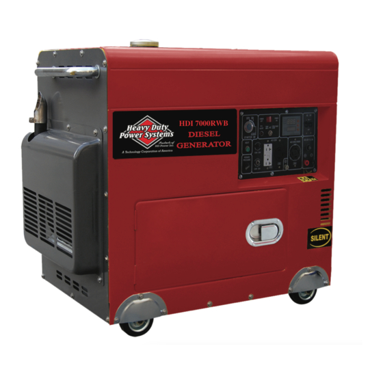
- Page 1 OWNER’S MANUAL AIR-COOLED DIESEL GENERATOR SET Model HDI 7000RWB Heavy Duty Power Systems Phone#:208-949-1121...
- Page 2 PREFACE PREFACE Thank you for purchasing products from our company .We appreciate your business. The following manual is only a guide to assist you and is not a complete or comprehensive manual of all aspects of maintaining and repairing your generator. The equipment you have purchased is a complex piece of machinery.
-
Page 3: Table Of Contents
TABLE OF CONTENTS TABLE OF CONTENTS Chapter 1 Technical Specifications and Data ……………………….1 1-1 Technical specifications and data…………………………………….1 1-2 Basic operating parameters……………………………………………2 1-3 General dimensions and overview of the generators……………….2 Chapter 2 Operating the Diesel Generator …………………………...3 2-1 Main points of safety during operation of the generator..…………..3 2-2 Preparation before operation………………….………………………4 2-3 Checking the operation of the diesel engine….……………………..7 2-4 Starting the generator set…………………….………………………..7... -
Page 4: Chapter 1 Technical Specifications And Data
TECHNICAL SPECIFICATIONS AND DATA CHAPTER 1 TECHNICAL SPECIFICATIONS AND DATA 1-1 Technical specifications and data H.D Single-cylinder diesel generator Model HDI7000BD HDI 7000RWB Item Rated frequency (Hz) 220、230、240、110/220、 Rated voltage (V) 380/220、 400/230、 420/240 115/230、120/240 Rated output power (kVA) Max output power (kVA) -
Page 5: Basic Operating Parameters
<3280.8 (<1000 m) 41~104 (5-40 1-3 General dimensions and overview of the generators 1-3.1 HDI 7000RWB dimensions of the series generator. 1-4 Operation Instruction see figure 1 Turn the switch “POWER” and circuit breaker switch “AC SW” to “OFF” position. - Page 6 Fill in small sum of fuel into the fuel tank, make sure fuel pipe is connected properly, and no leakage in fuel supply system. Fill in fuel to proper level. Connect the positive(+) battery cable to the battery positive(+) terminal. Connect the other end of the positive (+) battery cable to the generator positive (+) terminal.
- Page 7 1-4.3 Fault code E01—start failure (Starting directive is sent to controller, but generator fails to start. The generator will not try to start generator before fault is cleared) E02—voltage > 250V (The data is detected 5 seconds after generator starts) E04—frequency >67Hz (The data is detected 5 seconds after generator starts) E05—frequency<53Hz (The data is detected 5 seconds after generator starts) E06—battery voltage >19V (The data is detected before starting,.
-
Page 8: Chapter 2 Operating The Diesel Generator
OPERATING THE DIESEL GENERATOR CHAPTER 2 OPERATING THE DIESEL GENERATOR 2-1 General main points of safety during operation of the generator set. In order to operate the generator set safely, please follow all the instructions provided in this manual carefully. Doing so otherwise may lead to accidents or equipment damage. -
Page 9: Preparation Before Operation
Otherwise it will clog the fuel lines and oil nozzles. It may also damage your pressure pump. Note: It is dangerous to overfill the fuel tank. Never exceed the red piston in the filter. Type HDI 7000RWB HDI 7000RWB The effective volume of 14.5 14.5 fuel tank: (L)(US. - Page 10 OPERATING THE DIESEL GENERATOR 2-2.2 Filling engine oil Remove the dipstick from the engine Make sure the generator is on level ground, and fill the engine with 15W40 engine oil. Put the dipstick back into the hole to check the engine oil level. Engine oil is the most important factor in determining the life of your generator engine.
- Page 11 OPERATING THE DIESEL GENERATOR 2-2.3 Checking the air filter (1) Loosen the butterfly nut, take the cover of the air filter off and take the air filter element out. Do not use detergent to wash the air filter element. When the performance of the engine decreases or when the color of the exhaust gases is bad, exchange the filter element.
-
Page 12: Checking The Operation Of The Diesel Engine
OPERATING THE DIESEL GENERATOR 2-3 Checking the operation of the diesel engine 2-3.1 Low-pressure alarm system. H.D diesel engines have a low-pressure sensor system where if the oil pressure drops too low, the sensor will shut the engine off. The purpose of having this system is to ensure that the engine does not seize up. -
Page 13: Proper Operation Of The Generator Set
OPERATING THE DIESEL GENERATOR 2-4.2 Battery 1. Insert key into ignition and put it in the “off” position. 2. Put the speed handle in the “Run” position. 3. Turn the start switch clockwise to the “START” position. 4. After the diesel engine is started, remove your hand from the switch handle; the switch will automatically reset itself to the “ON”... -
Page 14: Loading
OPERATING THE DIESEL GENERATOR 3. Do not adjust the speed limit regulation bolt or the fuel adjustment bolt. These bolts have been set by the factory already, changing them will affect the properties of the engine performance. 2-5.2 Checks during engine operation 1. -
Page 15: Stopping The Generator
OPERATING THE DIESEL GENERATOR 2-6.3 Charging the battery 1. For the electric starter on the generator sets, the 12V battery is automatically charged through the regulator on the side of the engine when it is running. 2. If the generator is not used for long periods of time, the battery should be disconnected to avoid energy loss from the battery. -
Page 16: Chapter 3 Maintenance
MAINTENANCE CHAPTER 3 MAINTENANCE 3-1 Maintenance schedules Keeping your generator well maintained will prolong the life of your generator. Everything needs to be checked including the diesel engine, generator, control cabinet, and frame. For overhauling procedures, please refer to the instruction manual of the relative subassembly. If you need these manuals, please call our company and we will send you one. -
Page 17: Storing For Long Periods Of Time
MAINTENANCE 3-1.1 Changing the engine oil (every 100 hours) Take the oil cover off. Remove the oil drain plug when the diesel engine is still hot. Be careful of hot oil and hot engine as you may get burned. The bolt is located at the bottom of the cylinder. After draining the oil, put the bolt back and tighten it. -
Page 18: Chapter 4 Troubleshooting
TROUBLESHOOTING CHAPTER 4 TROUBLESHOOTING 4-1 Troubleshooting procedures Causes of malfunction Remedy Not enough fuel Add enough fuel The switch of fuel is not at Turn the switch of fuel to “OPEN” “OPEN” position. position. High-pressure pump and nozzle Disassemble the nozzle and adjust it do not inject fuel or the injected at test table. -
Page 19: Chapter 5 Generator Parts Diagrams And Listings
GENERATOR PARTS DIAGRAMS AND LISTINGS CHAPTER 5 GENERATOR PARTS DIAGRAMS AND LISTINGS Figure 5-1. Overall view of engine generator assembly... - Page 20 GENERATOR PARTS DIAGRAMS AND LISTINGS Table 5-1. Please refer to figure 5-1 for illustration Part Description Quantity Part Code Silencer cover HDI 7000RWB- Silencer bend HDI 7000RWB- Left board of cover HDI 7000RWB- Back door of cover HDI 7000RWB- Fixing sleeve for observing bore...
- Page 21 GENERATOR PARTS DIAGRAMS AND LISTINGS Part Description QU.T Part Code clamp of accumulator with bolt and nut HDI 7000RWB- cover of clamp of accumulator HDI 7000RWB- Alternator assembly HDI 7000RWB- Output wind leading shaft HDI 7000RWB- HDI 7000RWB- HDI 7000RWB-...
- Page 22 GENERATOR PARTS DIAGRAMS AND LISTINGS Figure 5-2. Electric panel parts drawing...
- Page 23 GENERATOR PARTS DIAGRAMS AND LISTINGS Table 5-2. Please refer to Figure 5-2 Number Part Description Quantity Part Code Nut M4(GB/T6170-2000) HDI 7000RWB -C-001 Electric start switch HDI 7000RWB -C-002 Square American type-socket HDI 7000RWB -C-003 Overload protector(20A) HDI 7000RWB -C-004...
- Page 24 GENERATOR PARTS DIAGRAMS AND LISTINGS Figure 5-3. Generator head assembly Table 5-3. Please refer to figure 5-3 Number Part Description Quantity Part Code Front end cover HDI 7000 RWB-B-001 Diode 3510 HDI 7000 RWB-B-002 HDI 7000 RWB-B-003 Bolt M5 x 16 Fan Blade HDI 7000 RWB-B-004 HDI 7000 RWB-B-005...
-
Page 25: Chapter 6 Circuit Diagram
CIRCUIT DIAGRAM CHAPTER 6 CIRCUIT DIAGRAM...
Need help?
Do you have a question about the HDI 7000RWB and is the answer not in the manual?
Questions and answers
How to install new brushes and regulator