Direct Fly Alto 912 TG Pilot Operating Handbook
Hide thumbs
Also See for Alto 912 TG:
- Aircraft maintenance manual (119 pages) ,
- Pilot operating handbook (48 pages)
Table of Contents
Advertisement
Quick Links
Advertisement
Table of Contents

Related Manuals for Direct Fly Alto 912 TG


Summary of Contents for Direct Fly Alto 912 TG
- Page 1 The Direct Fly Alto 912 TG PILOT´S OPERATING HANDBOOK DFE-POH-AR1...
- Page 2 PILOT´S OPERATING HANDBOOK 912 TG ALTO Aircraft model / modification Manufacturer : Direct Fly s r.o. DF051 Airplane Serial Number: Airplane Registration Number: PU-RJR Issued on : February 27, 2015 Revision : This aircraft must be operated following the instruction and limitation stated in this flight manual.
- Page 3 Publication number is now using the Direct Fly / Erres Industria Aeronautica Jul 20, 2014 patern. Revised to comply with the Brazilian version of the Alto 912 TG. Revised List of Supplements. Feb 27, 2015 Revised list of ASTM Consensus Standards DFE-POH-AR1 Rev.
-
Page 4: Table Of Contents
PILOT´S OPERATING HANDBOOK TABLE OF CONTENTS INTRODUCTION ASTM Standards ……….…………………………………..…………......………….…..……. i Contact Information ………………………………………………….……………......…………... i Data Location …………………………………………………………………………......……….. ii Section 1— GENERAL INFORMATION ....................... 1-0 Introduction to the Alto TG 912 ....................1-0 1.1.1 Side, Top and Front Views...................... 1-0 Performance Specifications ..................... - Page 5 PILOT´S OPERATING HANDBOOK 4.1.4 Right Wing ..........................4-0 4.1.5 Empennage and Fuselage ....................... 4-0 4.1.6 Left Wing ..........................4-1 4.1.7 Undercarriage .......................... 4-1 Engine starting ......................... 4-1 4.2.1 Engine warm up and Test ......................4-1 Taxiing ............................. 4-2 Normal Takeoff ........................4-2 Climb ............................
- Page 6 PILOT´S OPERATING HANDBOOK Flight instruments ........................7-3 Engine ............................. 7-5 Propeller ..........................7-5 Section 8 —HANDLING AND SERVICING ....................8-0 Introduction ..........................8-0 Ground handling ........................8-0 Towing ............................. 8-0 Tie-Down ..........................8-0 Servicing ..........................8-1 8.5.1 Fueling ............................. 8-1 8.5.1.1 Approved fuel grades and specifications .................
-
Page 7: Introduction
Standard Specification for Design and Testing of Light Sport Aircraft Propellers Designation: ASTM F2339-06 Standard Practice for Design and Manufacture of Reciprocating Spark Ignition Engines for Light Sport Aircraft Contact Information Company headquarter: Direct Fly s.r. o. Špitálka 8 602 00 Brno, Czech Republic www.directfly.cz info@directfly.cz The Manufacturing Facility: Direct Fly s.r.o. -
Page 8: Data Location
PILOT´S OPERATING HANDBOOK www.erresaeronautica.com.br contato@erresaeronautica.com.br Data Location Company headquarter: Direct Fly s.r. o. Špitálka 8 602 00 Brno, Czech Republic DFE-POH-AR1 Rev. 2... -
Page 9: Section 1- General Information
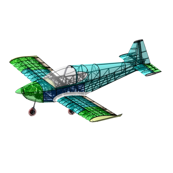
1.1 Introduction to the Alto Direct Fly ALTO 912 TG is an all-metal low wing aircraft with a riveted aluminum structure. Some non- load bearing parts such as the engine cowling, wing tips, empennage tips, and wheel covers are made of composite materials. -
Page 10: Performance Specifications
PILOT´S OPERATING HANDBOOK 1.2 Performance Specifications AIRSPEEDS FOR NORMAL OPERATION Takeoff: ..............45 KIAS Climb: Normal: ..............65 KIAS Best Rate of Climb (Vy): ........60 KIAS Best Angle of Climb (Vx): ........50 KIAS Design Cruise Speed (Vc): ........110 KIAS Landing Approach: Flaps 0º: ............. -
Page 11: Rate Of Climb
PILOT´S OPERATING HANDBOOK 1.2.4 Rate of climb Vx – Best Angle of Climb Airspeed to achieve best angle of climb Altitude Rotax 912 ULS (KIAS) 15.8 fps Sea Level 948 fpm Vy –Best Rate of Climb Altitude Rotax 912 ULS Airspeed to achieve best rate of climb (KIAS) 17 fps Sea Level... -
Page 12: Section 2 -Limitations
PILOT´S OPERATING HANDBOOK Section 2 — LIMITATIONS Airspeed Indicators Marking Marking IAS, Kts Meaning Operating range with extended flaps. Lower limit – Vs at maximum White Arc 35 – 70 weight (flaps 45°) Upper limit – V Green Arc 41 – 110 Normal operation range Lower limit –... -
Page 13: Approved Maneuvers
PILOT´S OPERATING HANDBOOK Approved Maneuvers • Steep turns up to bank angle of 60° • Climbing turns • Lazy eights • Stalls (except for steep stalls) • Normal flight maneuvers • Entry speed into maneuvers 89 kts. Total Fuel Capacity, Approved Fuel Grades 2.6.1 Fuel Capacity Usable fuel –... -
Page 14: Section 3 - Emergency Procedures
PILOT´S OPERATING HANDBOOK Section 3 — EMERGENCY PROCEDURES General Information This section covers the recommended procedures to follow during emergency and adverse flight conditions. Emergency situation arising from engine failure are highly unlikely if pre-flight checks and maintenance are properly performed according to the aircraft and engine manuals. Proper flight planning and using good judgment can minimize or reduced emergencies caused by poor or unexpected weather conditions. -
Page 15: Precautionary Landing With Engine Power
PILOT´S OPERATING HANDBOOK 3.3.4 Emergency Landing Without Engine Power Airspeed ................67 kts Trim ................... adjust Landing site selection ............select Make sure the engine failure is not a consequence of unintentional switching off the ignition, or fuel valve. Try to restart the engine using 3.3.16 In-Flight Engine Starting, if altitude permits, otherwise proceed with emergency landing using 3.3.2 Engine Failure during Take-Off. -
Page 16: Emergency Descent
PILOT´S OPERATING HANDBOOK 3.3.9 Emergency descent Power ................Idle Optimum gliding speed ............. 67 kts Flaps .................. as needed Best glide ratio (at 67 kts) ..........1:9 3.3.10 Alternator Failure Turn OFF all the non-essential equipment. You have approximately 30 minutes of battery, NOTE time. -
Page 17: Loss Of Flight Controls
PILOT´S OPERATING HANDBOOK 3.3.15. Loss of Flight Controls • Such type of failures are extremely rare if pre-flight checks and maintenance are properly performed according to the aircraft Manuals. Primary flight controls failures can potentially be caused by the following: •... -
Page 18: Section 4 - Normal Procedures
PILOT´S OPERATING HANDBOOK Section 4 — NORMAL PROCEDURES Preflight Check List Fig 4-1: Preflight check list 4.1.1 Cockpit Canopy Glass ............... check Master Switch ............... Ignition Switches ..............Control Lock ................. NOTE: If this is to be a night flight, turn Master Switch ON and check nav, strobes, and landing light. 4.1.2 Power Unit Engine, Propeller –... -
Page 19: Left Wing
PILOT´S OPERATING HANDBOOK Rudder ................. check (see note below) Fuselage surface, tail skid ............ check for damage NOTE: Nose wheel steering is connected to the rudder pedals. Do not try to deflect the rudder by hand. 4.1.6 Left Wing Surface & wing tip ..............check condition Flaps –... -
Page 20: Taxiing
PILOT´S OPERATING HANDBOOK Taxiing Do not use excessive speed when taxiing. Always check brakes at the beginning of movement. Normal Take-Off Brakes .................. as required Trim ..................neutral Flaps ..................take-off position Master Switch ............... Ignition .................. ON (L+R) Fuel Pump ................Fuel Quantity ................ -
Page 21: Approach
PILOT´S OPERATING HANDBOOK During cruising flight, an RPM of 4200 – 5500 RPM should be used (redline is 5800 RPM), monitor your fuel consumption and total fuel on board for flight planning. Always properly switch between tanks to supply fuel to the engine. When both tanks are full or nearly full, use RIGHT tank first. -
Page 22: Engine Cooling And Stop
PILOT´S OPERATING HANDBOOK 4.8.6 Engine Cooling and Stop Throttle ................. cool engine, approx. 2,000 rpm Flight instruments switch ............. Ignition .................. L then R OFF Master Switch ............... Alternator Switch ..............Fuel Valve ................Secure Aircraft ..............use tie downs and lock controls 4.8.7 Check After Flight Check overall aircraft condition... -
Page 23: Section 5 - Performance
PILOT´S OPERATING HANDBOOK Section 5 — PERFORMANCE Flight performances figures stated in this manual are valid for aircraft of standard version with maximum take-off weight of 1,320 lbs (600kg) assuming average pilot and ISA conditions (15°C/59°F temperature, 29.92” Hg pressure). Actual performances of your aircraft might vary according to pilot skills, weather and aircraft condition. -
Page 24: Airspeed System Calibration
PILOT´S OPERATING HANDBOOK RPM settings and Fuel Comsumption The following table lists fuel consumption, endurance and range at 3,000‘ MSL. Endurance and range are with 45 minutes of fuel reserves remaining Engine RPM 4,200 rpm 4,500 rpm 4,800 rpm 5,000 rpm 5,200 rpm 5,500 rpm Fuel consumption,... -
Page 25: Section 6 - Weight And Balance And Equipment List
PILOT´S OPERATING HANDBOOK Section 6 — WEIGHT AND BALANCE AND EQUIPMENT LIST 6.1 Weight and Balance Chart Fig 6-1: Weight and Balance CG reference plane is at the firewall Nose Gear weight R .................... = 53.5 kg (117 lbs) Left Main Gear weight R ................... - Page 26 PILOT´S OPERATING HANDBOOK This Weight and Balance information is for Aircraft DF051 PU-RJR Item Weight Moment Nose Gear -11.8 -1392 Left Gear 43,3 11994 Right Gear 43,3 12297 Empty Weight 33,7 22882 Fuel 28.3 Pilot 43.3 Copilot 43.3 Baggage 66.3 Totals 33,7 22882...
-
Page 27: Installed Optional Equipment List
PILOT´S OPERATING HANDBOOK 6.3.1 Empty Weight Approved empty weight range ............650 – 750 lbs 6.3.2 Aircraft CG Use the following to calculate aircraft CG. for Aircraft DF051 PU-RJR Empty Weight 33,7 22882 Fuel 28.3 Pilot 43.3 Copilot 43.3 Baggage 66.3 Totals CG limits = 34.4 –... -
Page 28: Section 7 - Description Of Airplane And Systems
Section 7 — DESCRIPTION OF AIRPLANE AND SYSTEMS General Direct Fly ALTO 912 TG is a single-engine, low-wing, cantilever monoplane, all-metal, with a riveted aluminum structure aircraft. Some non-load bearing parts such as the engine cowling, wing tips, empennage tips, and wheel covers are made of composite materials. The Alto is powered by the ROTAX 912 ULS engine (100 hp) and Woodcomp Propuls three-blade ground-adjustable propeller. -
Page 29: Wings
PILOT´S OPERATING HANDBOOK 7.2.1. Wings The rectangular wing is a monospar construction with an auxiliary spar. The skin is made from duralumin sheet. The wing is equipped with ailerons, flaps and integral fuel tanks with a total capacity of 96 l. All the elements are riveted together. The wing-body attachment forms a wing centre section, which is firmly placed into the fuselage. -
Page 30: Aileron Trim Tab Control
PILOT´S OPERATING HANDBOOK 7.3.5 Aileron Trim Tab Control (Optional) A electric aileron trim control is located on the top of both pilot and co-pilot sticks, which controls a trim tab on the “Right” aileron trailing edge, a servo on the aileron is interconnected to the trim tab by means of a push rod and clevis arrangement. -
Page 31: Instrument Panel
PILOT´S OPERATING HANDBOOK Instrument Panel The instrument panel is made of Carbon fiber with a aluminum face plate which support the components. The ALTO may be customised with several different instrument panels. A typical primary layout is shown below: Fig. 7-2: Primary Instrument Panel Flight Instruments / Controls INSTRUMENTS / CONTROLS LIST Control Sticks... - Page 32 PILOT´S OPERATING HANDBOOK 7.5.1 Instrument Markings 7.5.1.1 Airspeed Marking IAS, Kts Meaning Operating range with extended flaps. Lower limit – Vs at maximum White Arc 35 – 70 weight (flaps 45°) Upper limit – V Normal operation range Lower limit – V at maximum weight (flaps Green Arc 41 - 110...
-
Page 33: Engine
PILOT´S OPERATING HANDBOOK Marking Pressure Meaning 0.8 BAR Red Line Minimum limit - Do not operate the airplane under this mark. 12 PSI 0.8 – 2 BAR Yellow Arc Precautionary range – Below 3500 RPM 12 – 29 PSI 2 – 5 BAR Green Arc Normal operation range –... -
Page 34: Section 8 -Handling And Servicing
PILOT´S OPERATING HANDBOOK Section 8 — HANDLING AND SERVICING Introduction This section includes the procedures for airplaine handling, maintenance and operation recommended by the manufacturer. It is advisable to park the aircraft inside a hangar, or eventually inside a other weather proof space (such as a garage) with stable temperature, good ventilation, low humidity and a dust-free environment. -
Page 35: Servicing
PILOT´S OPERATING HANDBOOK When the aircraft is parked (on the ground, stowed), position a pitot cover over the pitot-static tube to prevent wind gusts and contamination from entering the pitot port. A red flag must be attached to the pitot cover. -
Page 36: Approved Fuel Grades And Specifications
PILOT´S OPERATING HANDBOOK It is highly recommended to pour gasoline through a filter if it was not tested for water content. After fueling, allow 20 min. for water to settle out on the bottom. Drain off some fuel and look for water. 8.5.1.1 Approved Fuel Grades and Specifications •... -
Page 37: Approved Oil Grades And Specifications
PILOT´S OPERATING HANDBOOK 8.5.2.1 Approved Oil Grades and Specifications Motor oils tested and released from BRP-powertrain (for use with unleaded fuel or MOGAS). Shell Sport Plus 4 API SL SAE 10 W-40 Code 2. Refer to the ROTAX engine Operator’s Manual - Section 2.5 8.5.3 Coolant The expansion reservoir located in the engine compartment attached to the firewall is used for filling the coolant. -
Page 38: Brake Fluid
PILOT´S OPERATING HANDBOOK 8.5.4 Brake Fluid A brake fluid is filled into reservoir located below the central panel between the seats - see "C" on the picture below. For the minimum and maximum brake fluid level – see picture below. Brake fluid refilling is necessary when a low brake system efficiency occurs due to a fluid leak. -
Page 39: Recommended Type Of Brake Fluid
PILOT´S OPERATING HANDBOOK Instructions: - see the picture above 1. Disconnet the brake grip A 2. Remove screws B 3. Open the central panel C 4. Check brake fluid quantity and fill some amount if needed. 5. Brake repeatedly on the brake lever during refilling. Bleed the system after refilling. 6. -
Page 40: Section 9 - Supplements
PILOT´S OPERATING HANDBOOK Section 9 — SUPPLEMENTS Aditional Information regarding the Airplane 9.1.1 Tire inflation pressure Tire pressures are noted on placards located on the airplane Landin Gears. A car tire pump or compressor, or pressure bottle may be used for inflating the wheels. Nose wheel Tire .......... - Page 41 PILOT´S OPERATING HANDBOOK One of the following placards is located on the sidewall of the canopy rail: Day VFR airplane The airplane is approved only for VFR daylight flights under no icing conditions. Or (Night VFR airplane) The airplane is approved only for VFR day and night flights under no icing conditions.
-
Page 42: Operation Of Optional Equipments Or Accessories
PILOT´S OPERATING HANDBOOK Operation of Optional Equipments or Accessories This section contains the appropriate supplements necessary to safely and efficiently operate the airplane when equipped with various optional systems and equipment not provided with the standard airplane. 9.2.1 List of Supplements Title of Supplement Supplement No. -
Page 43: Airplane Flight Training Supplement (Fts)
However, the final decision on their adoption or otherwise rests with Direct Fly S.R.O. Any issues or corrections required of Direct Fly S.R.O. on publications are requested to be passed on to Direct Fly S.R.O. or its Completion Facilities on the adresses listed in the INTRODUCTION. The following proforma may be used: DFE-POH-AR1 Rev. -
Page 44: Continued Operational Safety Reporting
The owner/operator of a LSA is responsible for notifying the manufacturer of any safety of flight issue or significant service difficulty upon discovery. The following proforma may be used & sent to Direct Fly S.R.O. or its Completion Facilities on the adresses listed in the INTRODUCTION. -
Page 45: Owner Change Of Adress Notice
Each owner/operator of a LSA is responsible for providing the manufacturer with current contact information where the manufacturer may send the owner/operator supplemental notification bulletins. The following proforma may be used & sent to Direct Fly S.R.O. or its Completion Facilities on the adresses listed in the INTRODUCTION.
Need help?
Do you have a question about the Alto 912 TG and is the answer not in the manual?
Questions and answers