
Subscribe to Our Youtube Channel
Summary of Contents for Hofmann PMH-2
- Page 1 DIGITAL pH / ORP / mV CONTROLLER PMH-2 USERS GUIDE PMH-2 Instruction manual PAGE 1...
-
Page 2: Table Of Contents
OPERATION ....19 Initial check of the PMH-2... 19 Calibrating the PMH-2 with a simulator..19 Selecting Mode of Operation. -
Page 3: Specifications
Selected for Relay1 through setup program. Pulse width adjusts automatically to suit dosing require- ments. On time varies from continuous to minimum 1 second. Pulse interval increases / decreases to fur- ther fine-tune a dosing cycle. PMH-2 Instruction manual PAGE 3... - Page 4 240VAC (A, N, E) located next to potential free contacts allows for easy wiring of this terminal. Housing: Fully sealed construction with hinged clear acrylic front cover. IP55 specifications. Dimensions: 166mm x 160mm x 105mm. PAGE 4 PMH-2 Instruction manual...
-
Page 5: Introduction
INTRODUCTION The new PMH-2 controller features a simple and safe way for all configuration and calibration procedures. All programmed parameters are stored in non-volatile memory and are not lost if the instrument looses power. You use the ‘rotary encoder knob’ to scroll through setup menus and dial up/down numbers when prompted to enter values for relay or alarm setpoints, current signal low and high points etc. -
Page 6: Normal Dosing (Nor)
Up or down dosing is possible with normal proportional dosing. Adaptive proportional dosing. (Ad.P) The relay output of the PMH-2 instrument is controlled through a complex algorithm that continuously monitors the difference between actual pH / mV and set point. The output starts to pulse and varies the... - Page 7 Up or down dosing is possible with “Adaptive proportional Dosing”. ! If using AdP the second relay must be configured as alarm ! The PMH-2 program prevents gross overdosing in the event of a process upset or electrode failure. (Adaptive mode only)
- Page 8 A PT-100 temperature electrode connected to the terminals enables the option for automatic compensation. The PMH-2 features an alarm relay with potential free contacts. Low and high alarm points are set in the configuration menu. ALARM/Relay2 can also be configured to perform as a second setpoint relay in either up or down mode.
-
Page 9: Installation
Select a position for the controller to be mounted on a wall, not facing into direct sunlight and protected from the weather elements as much as possible. The PMH-2 should be installed near the treatment plant. Maximum length of the co-axial cable used should not exceed 10 metres because of the very high input impedance characteristic of a pH electrode. -
Page 10: Wiring Of The Pmh-2
Polarity does not matter when wiring a flow switch. The Set point relay terminals connect to earth, neutral and switched active 240V. (240VAC is supplied to these terminals when activated by the set point.) FIG 4 Terminal layout for the PMH-2 PAGE 10 PMH-2 Instruction manual... -
Page 11: Signal Output
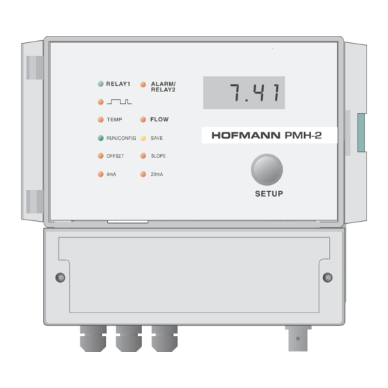
After you have installed the instrument and checked all the wiring and connections open the isolation valves to the sensor to allow water flow across it. Plug the power cord into the supply and switch on the PMH-2. The “RUN/CONFIG” LED will light up green and the digital display shows the measured input value. -
Page 12: Configuration
CONFIGURATION Looking at menus and values without changing or saving. The PMH-2 is now in ‘RUN’ mode and processes the mV signal, output and alarm relays and the signal output. This condition is indicated with the green ‘RUN/CONFIG’ light. Turning the encoder knob has no effect. -
Page 13: Default Values For The Pmh-2 Instrument
Default values for the PMH-2 instrument The PMH-2 is shipped with default values programmed in non-volatile memory. mV MODE Dosing = UP Setpoint = 700 Dosing Mode = normal dosing no.d Low Alarm mV = 200 High Alarm mV = 1000... -
Page 14: Saving Values In Configuration
C mode. ‘PUSH’ and dial up the new temperature. Range is 0 to 100 Connecting a PT100 temperature sensor enables the PMH-2 to use automatic compensation. Select SoC for manual or AoC for auto com- pensation. In AoC mode the actual temperature is displayed. - Page 15 When all configurations are done step to the next menu [End] to exit. ‘PUSH’ returns to operating mode. The PMH-2 always returns to operating mode after 2 minutes if left in configuration or calibration mode.
- Page 16 PAGE 16 PMH-2 Instruction manual...
- Page 17 PMH-2 Instruction manual PAGE 17...
- Page 18 8.5 or in mV mode between 280mV and 900mV. The message ‘ Err ‘ will show if this condition is not met. If this is the case PUSH twice, adjust pH / mV for correct value and repeat mV calibration. PAGE 18 PMH-2 Instruction manual...
-
Page 19: Operation
“RELAY OUTPUT” LED at the programmed setpoint. Calibrating the PMH-2 with a simulator. The operator should be familiar with the different effects if OFFSET and SLOPE calibrations are carried out. Offset adjustments increase or de- crease the reading regardless of the absolute measured value. - Page 20 The use of redox buffers therefore is restricted to a simple function test of a redox electrode. The mV offset and mV slope calibration modes of the PMH-2 are mainly used to correct minor instrument offset or gain errors of the input section.
-
Page 21: Selecting Mode Of Operation
PUSH’ turns on the SLOPE (right side) LED. ‘PUSH’ again, the LED now flashes and the display shows “live” mV input. ‘Rotate’ until the correct mV value shows on the display and ‘SAVE’. The mV reading of the PMH-2 is now accurate. - Page 22 Setting the gradient to the maximum of 100 starts the output relay pulsing when 0.5pH (10 mV) below/above setpoint giving a very steep gradient. The on/off ratio reduces very rapidly. (See Fig.6) for ‘gradient’ versus pulse output. PAGE 22 PMH-2 Instruction manual...
- Page 23 1.5 to 30 seconds. Up or down mode is possible with Adaptive Proportional dosing. The time taken for the PMH-2 to register the neutralising effect of the chemicals injected depends on the mixing and retention time of the plant installation.
- Page 24 Select CL mode for this type of switch. If it is not certain what type of switch is in the system operate the PMH-2 and configure for OP or CL until normal operation of the relay output is established with water flowing.
- Page 25 Enter calibration [CAL] and ‘Rotate’ until the 4mA LED lights up. ‘PUSH’ to enter 4mA calibration. The display shows 4.00. Dial the measured mA with ‘Rotate’. ‘SAVE’ and the actual current is corrected to 4.00mA. Move PMH-2 Instruction manual PAGE 25...
- Page 26 Using the PMH-2 as a 4-20mA Simulator Entering 4.20 mode enables the operator to sweep the 4 to 20mA signal current for testing, setting up or calibrating an installation for accurate and correct performance between signal output and connected appliance or computer interface.
-
Page 27: Pmh-2 And Swimming Pools
(Fig.11) The PMH-2 monitoring a metal electrode controls the liquid chlorine for the pool. Chlorine is a caustic liquid and increases the pH level when added to the pool water. The PMH-2 connected to a pH electrode maintains pH at 7.2 to 7.6 by dosing acidic neutraliser. The electrodes are installed in a drain configuration, drawing off a small amount of pool water. -
Page 28: Warranty
WARRANTY We, HOFMANN ELECTRONICS, guarantee this unit against de- fects due to faulty manufacture or breakdown of components for a period of twelve month from the date of purchase, subject to the following provisions: ° The guarantee will cover original failure of parts and natural defects due to manufacturing causes.
Need help?
Do you have a question about the PMH-2 and is the answer not in the manual?
Questions and answers