
Summary of Contents for Technik-Plus FRONT-TURBO
- Page 1 Instruction for seeder “FRONT-TURBO” *Translation from original* TECHNIK-PLUS Sämaschinen e.U. Industrieparkstrasse 6-8 A-8480 Mureck www.technik-plus.eu Serial no.: office@technik-plus.eu Version 08/2020 Tel: + 43 3472 21 120...
-
Page 2: Table Of Contents
Content SAFETY ..................................3-6 MOUNTING ................................. 6-9 CHANGING OF SEED ROLL ............................10 BOTTOM FLAP, COVER SHEET ............................11 HYDRAULIC-SYSTEM ..............................12 HOW TO STORE CABLES CORRECT ..........................12 PROFICONTROL UNIT .............................. 13-15 SEEDER+ / TWIN UNIT ............................. 16-19 CHECKING POINTS ................................ 20 CLEANING AND SERVICE .............................. - Page 3 Product handover: Hand over the seeding machine just with the complete instruction. The user has to be informed by the seller in all details about the machine and its functions. He must be sure to work with the seeder safe. Do a short testing and check all the functions of the seeder.
- Page 5 First steps: Please check: 1. Has the seeder been damaged during transport? 2. Is everything delivered according to the delivery note? 3. Before starting read this instruction carefully and be sure you understand it. 3. Do the start up, control and service as written in the instruction. 4.
-
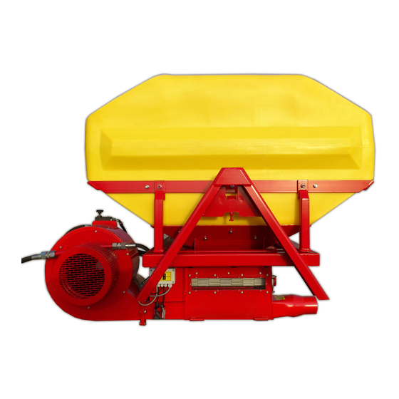
Page 6: Mounting
Be sure that the cables can’t be rubbed and overheated. Is the isolation damaged, change the cable immediately! Mounting and frame: Take care on following points when mounting the seeder: If the frame is made by your own it must have enough carrying capacity. During driving strong vibrations are coming to the seeder and frame ... - Page 7 Short description and shipment : see delivery note Techn. details: see technical data sheet Transport information: The seeder can be carried on the 4 mounting points. Take care that the belts for all 4 points have the same length and are strong enough. Are the differences in length too much the seed can overturn. You can also use the hopper frame for carrying.
- Page 8 TP-FRONT-TURBO mounting: Hoses can be led flat. Possible for: Grass, clover, mustard, rape, phacelia, oil radish, lucerne, …Up to 24m Working width 6 m TP-FRONT-TURBO High capacity seeder for seed fertilizer. Seeding with striegle up to 24m Fertilizer spreading on now crop culture up to 40 rows.
-
Page 9: Changing Of Seed Roll
The position oft he spreader plates can be Mounting the hose on the spreader plate. horizontal or vertical. Either horizontal Or vertical Changing of seed roll TP-TURBO-JET Super 6/10 1. Remove the covers for the gears! 2. Remove the gears – Remove marked *split pin! (Pict. 1) 3. - Page 10 8. Check the axial tolerance! (When the bottom flap is opened) Dear Ladies and Gentlemen! Plastic extends at high temperature and lowers less when cooling. Please check when using the machine: The seed roll must have axial play. The plastic gears must have 0,4 to 0,5mm play between plastic gear and hexagon (left and right side) seed axle.
- Page 11 Bottom flap: Bottom flap is closed = small seed z.B: grass seed, rape, oil radish, lucerne, … Open the bottom flap up to the marking for big seed z.B: vetch, pea, wheat, rye, oat, beans, sun flower, barley, buckwheat, … For emptying open the bottom flap complete.
- Page 12 Combination – Bottom flap with seed roll: Metall seed roll with Standard seed roll with plastic bottom flap. plastic bottom flap. Seed roll for small amount with stainless steel bottom flap with Between the plastic bottom flap and the seed roll should be a distance of stopper.
-
Page 13: Hydraulic-System
Hydraulic system with SEEDER+ control unit: Valve The hydraulic system on the fan is configured for max. 50lit/min and the motor for max. 25lit/min.If this amount is exceeded, the fan can be damaged. – NO WARRANTY! Put the return pipe and the leak oil line absolutely non-pressurised to the hydraulic. - Page 14 Important hints for laying cables: Put the cables in rolls! Don´t bend the cables near sockets! Take care when the implement is folded. Cable can breakaway or clamp! Avoid strong pulls on the cables! Don´t bend the cable not to strong. Avoid clamps on the cables. Use cable protection as needed! Mount the control unit in a good position to reach it easy.
-
Page 16: Proficontrol Unit
PROFI CONTROL UNIT On-/Off-sensor Cable to seeder Battery cable Speed knob: For adjusting the speed on the seed roll motor=adjusting of output amount. The amount cann be changed during operation The seed roll motor speed = output amount can be adjusted stepless with this Poty. This can be done during operation too to get the correct output amount. - Page 17 2. Main switch: This switch opens all functions on the unit. WHEN WORKING ON THE MACHINE DISCONNECT POWER SUPLY! 3. For switching ON/OFF the seed roll and fan: When pressing this button the fan turns on first and after some seconds the seed roll starts turning. Press the button again for switching off. The seed roll stops and after some seconds the fan turns off.
- Page 18 Mounting possibilities On-/Off-sensor Configuration plug: Electric fan Nr. 54: Blue cable (– from relay) Nr. 58L: Brown cable (+ from relay) Nr. 31: Cable No. 1 (– from the unit) Nr. 58R: Cable No. 2 (+ from the unit) Hydraulic fan Nr.
-
Page 19: Seeder+ / Twin Unit
SEEDER+ / TWIN Unit READ THE SEPERATE OPERATION INSTRUCITION AS WELL SEEDER+/TWIN Connection Connection to to battery battery Sensor cable with Sensor cable with red marking is for red marking is for on/off sensor on/off sensor (linkage sensor) (linkage sensor) The speed sensor reacts to metall. - Page 20 Check the impulses/signals before first use. Attention! The sensor must count every signal (light shines) (Pict 1) and switch off between the signals (light off) (Pict 2) Pict. 1: Light shines! Pict. 2: Light off! Errors: 1. If the light doesn´t shine the distance between sensor and metal can be to big (max. 4mm). 2.
- Page 21 It is possible to change the polarity from the on/off sensor. Check parameter no. 02 (Seeder+) respectively parameter no. 04 (TWIN) in the instruction for Seeder+/Twin. Mounting possibilities On-/Off-sensor The on/off sensor and speed sensor itself are the same except their diameters. One sensor has a diameter of 18mm and a reacting distance of max.
- Page 22 TURBO” with SEEDER+ control unit connect turbine sensor Seedroll motor On-/Off-sensor Seedroll sensor Speed sensor connect TURBO” with SEEDER+ control unit and Radar connect turbine sensor Seedroll motor Speed sensor On-/Off-sensor Seedroll sensor connect...
- Page 23 Signal connections: Signal plug cable Version A: On/Off signal blue brown & black Speed signal Some tractors have the speed signal on pin no. 1 and pin no. 2. In this case just connect to the radar signal. You can find more information regarding the configuration of the signal socket in the tractor´s instruction.
-
Page 24: Cleaning And Service
Working on the field: Hint: To achieve the best spreading, mix bad running grass seed with easy running seed or use mixtures which are highly productive for the soil and harvest. Before start working: Take the effort to calibrate the machine as written. Note the adjusting for future. If you use the Profi control unit, note the driven speed. - Page 25 ATTACHEMENT 1 SEED CHART TP-FRONT- TURBO Metal seed roll 5mm seed roll 10mm seed roll 15mm seed roll Standard seed roll Metal seed roll Metal seed roll (Crops, fertilizer, (Rape, clover, etc.) (Rape, clover, etc.) (Rape, clover, etc. ) (Mustard, etc.) (Peas) (Grass seed) etc.)
-
Page 27: Attachement 2 Declaration Of Conformity
ATTACHEMENT 2 Declaration of conformity... -
Page 28: Attachement 3: Warranty Request
ATTACHMENT 3 Warranty request CLAIMANT: Company/Name: ____________ Agent: ______ Address: Country: Phone number: E-Mail: Machine details: Typ: Serialno: Failure description (maybe with picture - E-Mails not over 4MB!!): DONE WORK – USED PARTS... - Page 29 Warranty Terms: The manufacturer warranty is 1 year and valid when: · within this time, spare parts are damaged because of wrong installation from the manufacturer or material defects. · using the original spare parts. The warranty expires when: · wearing parts must be changed in normal use regularly. ·...
Need help?
Do you have a question about the FRONT-TURBO and is the answer not in the manual?
Questions and answers