Advertisement
Quick Links
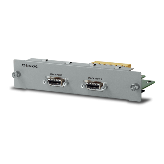
AT-StackXG Stacking Module
Installation Guide
Allied Telesis, Inc.
www.alliedtelesis.com
Overview
The AT-StackXG Stacking Module allows the formation of a stacked
configuration when installed in each switch in a group of AT-9400 Basic Layer
3 Gigabit Ethernet Series switches or x600 Layer 3 Gigabit Ethernet Series
switches. With its two full-duplex, 12-Gbps stacking ports, the module unifies
the individual switches of the stack into a single, logical unit so that the
network operations of the devices, such as spanning tree, port mirroring and
port trunking, encompass all of the Gigabit Ethernet ports. This can simplify
network management and augment network bandwidth.
AT -L X
A T- S ta
44 C P
ck X G
U C V R
St ac k
Po rt
1
St ac k
Po rt
2
Figure 1. AT-StackXG Stacking Module
*613-001122 RevA*
613-001122 Rev A
1
Preparation
Review the following information before installing the AT-StackXG Stacking
Module:
Caution
The AT-StackXG Stacking Module is sensitive to and can be damaged
by electrostatic discharge. Wear a grounding device and observe
electrostatic discharge precautions when installing the module in the
chassis.
❑ The AT-StackXG Stacking Module is hardware hot-swappable. You can
install or replace the module while the switch is powered on.
Caution
If the stacking module is added or replaced in an operating stack, the
stack topology may change and cause the stack to reboot and interrupt
network traffic.
AT-9400 Basic Layer 3 Gigabit Ethernet Switch Series :
❑ Do not install the module until you have read the latest version of the
AT-S63 Software Release Notes and the AT-9400 Series Stack Installation
Guide.
❑ The AT-StackXG Stacking Module is supported in the AT-9424Ts,
AT-9424Ts/XP, and AT-9448Ts/XP Basic Layer 3 Switches. All other
models in the AT-9400 Series do not support the HiGig stacking feature and
must be used as stand-alone switches.
❑ Support for the AT-StackXG Stacking Module requires Version 3.0.0 or
later of the AT-S63 Management Software.
x600 Layer 3 Switch Gigabit Ethernet Switch Series:
❑ The AT-StackXG Stacking Module is supported in all x600 series products.
❑ Do not install the module until you have read the latest version of the AW+
Software Release Notes and the x600 Series product documentation.
❑ Support for the AT-StackXG Stacking Module requires software version
5.3.1 or later of AlliedWare Plus.
Package Contents
The following items are included in the shipping package. If an item is missing
or damaged, contact your Allied Telesis sales representative for assistance.
❑ One AT-StackXG Stacking Module
❑ One AT-StackXG Stacking Cable (length - .5 m)
❑ Installation Guide
Warranty Information
1240
The AT-StackXG Stacking Module
www.alliedtelesis.com/warranty for the specific terms and conditions
of the warranty and for warranty registration.
has a Lifetime Warranty. Go to
2
Installing the AT-StackXG Stacking Module
To install the AT-StackXG Stacking Module, perform the following procedure:
1. Remove the module from the shipping package.
Note
Store the packaging material in a safe location. You must use the original
shipping material if you need to return the unit to Allied Telesis.
2. Remove the blank panel from the expansion slot on the back panel of the
switch by loosening the two captive screws on the panel with a cross-head
screwdriver.
AT -L X4
4C PU
CV R
Figure 2. Removing the Blank Panel from the Expansion Slot
Note
Do not remove the blank panel from the chassis until you are ready to
install a module. An open slot allows dust to enter the unit and reduces
proper airflow and cooling.
3. Align the edges of the module with the guides in the slot and carefully slide
the module into the chassis until it is flush with the back panel of the
chassis, as shown in Figure 3. Light pressure may be needed to seat the
module on the connector on the back panel of the chassis.
Caution
Do not force the module into place. Doing so may damage the
connector pins on the backplane inside the chassis. If there is
resistance, remove the module and reinsert it after verifying that the
edges of the card are properly aligned in the guides in the chassis'
module slot.
3
1241
Advertisement

Summary of Contents for Allied Telesis AT-StackXG
- Page 1 Do not remove the blank panel from the chassis until you are ready to port trunking, encompass all of the Gigabit Ethernet ports. This can simplify ❑ The AT-StackXG Stacking Module is supported in all x600 series products. install a module. An open slot allows dust to enter the unit and reduces network management and augment network bandwidth.
- Page 2 St ac k Po rt This Allied Telesis RoHS-compliant product conforms to the European Union Restriction of the Use of Certain Hazardous Substances (RoHS) in Electrical and Electronic Equipment. Allied Telesis ensures RoHS conformance by requiring supplier Declarations of Conformity, monitoring incoming materials, and maintaining...