Table of Contents
Advertisement
Quick Links
Advertisement
Table of Contents

Summary of Contents for sewerin ATS 503
- Page 1 ATS 503/501 Test set Operating Instructions...
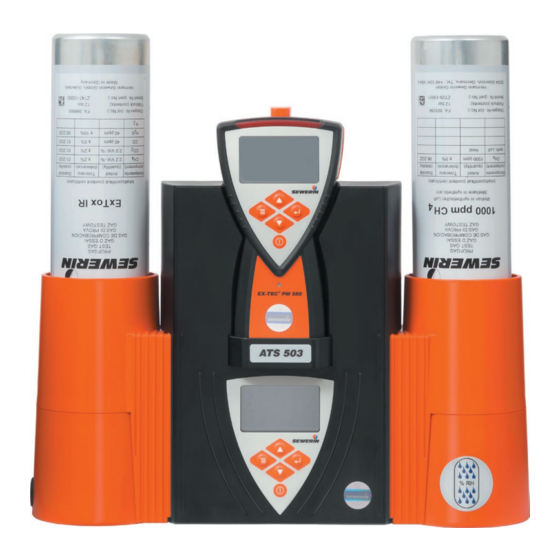
- Page 2 ATS 503/501 Locking mechanism Device holder Control panel Canister holder Fig. 1: ATS 503 – front view Display Menu key Up key Enter key Down key ON/OFF key Fig. 2: ATS 503/501 – control panel...
- Page 3 ATS 503/501 Air connection Test gas connections ATS 503 – view from above Fig. 3: Supporting bracket USB port Fig. 4: ATS 503 – tilted position Connection for power supply Cable guide ATS 503/501 – rear (section) Fig. 5:...
- Page 4 Illustration of warnings in this document NOTICE! Risk of damage to property.
-
Page 5: Table Of Contents
Cancel the action or process ..........22 4.4.5 Scrolling ................22 4.4.6 Select values ................23 4.4.7 Answer questions ..............23 4.4.8 Lists – view detailed information ..........24 Test gases ................25 Test gas connections for the test set ........25 5.1.1 ATS 503 ................25 5.1.2 ATS 501 ................26 Contents │... - Page 6 Utilisable test gases ..............26 Available test gases ..............27 Planning for gas assignment ...........27 Connecting test gases .............28 5.5.1 Screwing on the test gas can ..........28 5.5.2 Connecting a test gas bottle ..........29 Assigning test gases to test gas connections (gas assignment) ................29 Non-use of test set ..............30 Settings ..................31...
- Page 7 Features ..................46 Presentation of results ............46 Performing an adjustment ............47 Protocols and information ...........48 Protocols .................48 Information ................50 Maintenance of the test set ..........52 10.1 Servicing .................52 10.2 Care ..................52 10.3 Replacing the rubber gasket ...........53 Faults and problems .............54 11.1 Messages in the event of faults ..........54 11.2...
-
Page 8: Introduction
● Contradictory national legal regulations take precedence over the information in this document. Translations Translations are produced to the best of our knowledge. The original German version is authoritative. Right of reproduction No part of this document may be edited, duplicated or circulated in any form without the express consent of Hermann Sewerin GmbH. 1 Introduction │ 1... -
Page 9: Purpose
Registered trademarks Registered trademarks are generally not indicated in this docu- ment. Purpose The ATS 503 or ATS 501 test set can be used to perform the following maintenance activities: ● Device inspection ● Adjustment The test set is suitable for the following gas concentration meas- uring devices: ●... -
Page 10: Safety Information
● Use the product only as intended. ● Do not make any changes or modifications to the product unless these have been expressly approved by Hermann Sewerin GmbH. ● Only use accessories and consumables approved by Hermann Sewerin GmbH. ● Always observe the permitted operating and storage temper- atures. -
Page 11: Qualification Of Users
− Specialists are allowed to carry out the activities of trained per- sons and, in addition, commission the test set and configure the GasCom software. Competent person SEWERIN service personnel and people trained by SEWERIN are competent persons. − Competent persons have knowledge of the applicable regula- tions and guidelines as well as the tasks and functions of gas concentration measuring devices. - Page 12 − Competent persons must receive regular training. − Competent persons are allowed to carry out the activities of specialists and also to service the test set. 1 Introduction │ 5...
-
Page 13: Product Description
Product description Product variants The following product variants of the test set are available: ● ATS 503 ● ATS 501 The product variants differ in the number of test gas connections. ATS 503 ATS 501 Test gas connections (total) – for test gas cans – for test gas bottles –... -
Page 14: Visual And Audible Signals
The ambient air hose can be purchased as an accessory. The air connection is equipped with an internal carbon dioxide filter. The filter is tested by SEWERIN Service as part of the an- nual maintenance. Electrical connections The test set has the following electrical connections: ●... -
Page 15: Menu
Menu The menu (fig. 6) is accessed using the menu key. Which menu level is visible depends on the situation. In the menu the user can: ● Perform actions ● Perform settings ● View information ………….. Device inspection Warning Warning ECO Measuring Structure ………….. Adjustment Warning Measuring Structure ………….. ………….. Settings Gas assignment Gas 1 Gas 2... - Page 16 Information on some menu items ● Warning, Warning ECO, Measuring, Structure The menu items are only displayed if a device inspection/ad- justment is technically possible (section 1.4). If a device inspection/adjustment is not technically possible, the Warning menu item will be displayed. If this menu item is then selected, an error message will appear. ● All This menu item is only displayed if more than one device in- spection/adjustment is due.
-
Page 17: Preparing For Start-Up
Preparing for start-up Note: Start-up may only be carried out by specialist technicians. Suitable environment The test set may only be operated in spaces that meet the fol- lowing requirements: ● clean ambient air ● well ventilated ● dry ● dust-free ●... -
Page 18: Tilted Position
3.2.2 Tilted position The test set can be tilted. It is supported by the supporting brack- NOTICE! When tilted, the supporting bracket is not designed for forces applied from above. ● Never exert pressure on a test set that is tilted. Fig. 7: Setting up the test set in a tilted position (test set shown without canister holder and locking mechanism) 3 Preparing for start-up │ 11... -
Page 19: Wall Mounting
Setting up the test set in a tilted position (fig. 7) 1. Pull the supporting bracket down vertically. Remove the sup- porting bracket. 1 2. Plug the device plug of the AC/DC adapter into the power supply connection of the test set. 3. - Page 20 Fig. 8: Mounting the test set on a vertical surface (test set shown without canister holder and locking mechanism) 3 Preparing for start-up │ 13...
- Page 21 Mounting the test set on a vertical surface (fig. 8) 1. Pull the supporting bracket down vertically. Remove the sup- porting bracket. 1 2. Attach the supporting bracket to the surface. 2 − Using the supporting bracket, mark the 3 holes that need to be drilled. − The open side of the bracket must face the surface, the smooth side towards the user.
-
Page 22: Operation
Operation Switching on the test set The test set can be switched on as soon as it is connected to the power supply. ● Press the ON/OFF key. a) A sequence of start images (fig. 9) appears. b) The gas status (fig. 10) is displayed. c) The waiting mode (fig. 11) is displayed until the test set de- tects a device. The test set is ready for use in waiting mode. d) When the test set is switched on with the device inserted: −... - Page 23 Fig. 10: Gas status Fig. 11: Waiting mode Fig. 12: Inserted device de- tected (here: Manual operating mode, Device inspection menu) Special features at start-up Using the GasCom software you can specify that the following additional settings are made during start-up: ●...
-
Page 24: Switching Off The Test Set
Fig. 13: Language Special features with significantly modified test gas pressure When the test set is switched off, the pressure values of all con- nected test gases are saved. At the start of the next switch-on process, the saved values are compared internally with the cur- rent values. If there is a significant difference, then the gas as- signment must be carried out again after the start images (fig. 9). Switching off the test set Switching off the test set takes approx. 3 seconds. During the switch-off process, the display shows: − ATS switching off … message −... -
Page 25: Placing The Device In The Test Set
Placing the device in the test set NOTICE! Incorrect operation or damage to property in case of jamming The electrical contact of the device to the test set and the gas supply from the test set to the device can only be ensured if the device does not jam when inserted. -
Page 26: Navigating
3. Push the locking mechanism down completely. 3 − If the device was not switched on: The device will be switched on. − The device switches to charging mode. Note: When a battery-powered device is inserted in the test set, the bat- teries will be charged. The test set does not have to be switched on but connected to the power supply. - Page 27 Status area The status area covers the lower section of the information area. The symbols in the status area give an indication of the current situation. The selected operating mode is always displayed at the bottom. Fig. 17: Status area (black) Left image: Status area above the information area Alongside:...
-
Page 28: Key Functions
Fig. 18: Message Left image: Message The information underneath is covered. Right image: Example of a message (here: Information No device (PM) detected) 4.4.2 Key functions The following actions can be performed using the keys: Actions ● Switching – the test set on and off ● Changing –... -
Page 29: Switching Between Levels
4.4.3 Switching between levels Select a menu item in a menu The test set shows a menu. 1. Using the arrow keys, select the desired menu item. 2. Press the Enter key. The menu item appears. Switch from any menu level to the top menu level The display shows any menu level. 1. -
Page 30: Select Values
The display view has a scroll bar. ● Press the arrow keys to scroll. 4.4.6 Select values Values or symbols must be selected for certain settings. Fig. 20: Examples of selecting values/symbols Left image: Select numbers (here: Start time for timer) Right image: Tick or untick checkboxes (here: Days of week for timer) The program situation requires the selection of... -
Page 31: Lists - View Detailed Information
Note: Questions have different default settings for the answer. Fig. 21: Examples of questions Left image: Question with the default answer Yes Right image: Question with the default answer No The display shows a question. 1. Check the default answer setting. 2. Select the other response if necessary using the arrow keys. -
Page 32: Test Gases
Special features of test gas connection 3 The test gas connection is equipped with an internal conditioner. SEWERIN recommends using test gas connection 3 only for test gases for testing and adjusting gas-sensitive semiconductors. 5 Test gases │ 25... -
Page 33: Ats 501
Other test gases (e.g. ExTox IR) can quickly saturate the con- ditioner. 5.1.2 ATS 501 Fig. 23: ATS 501 – test gas connection Utilisable test gases All test gases suitable for the respective device and purpose can be used for device inspection and adjustment. These can be both gas mixtures and individual gases. With some test gases, par- ticularly gas mixtures, several gases can be tested or adjusted simultaneously. -
Page 34: Available Test Gases
Preset test gases Test gases are preset in condition at delivery. These SEWERIN test gases can be used to perform all the required device inspec- tions and adjustments. Information about the preset test gases can be found in sec- tion 12.2. -
Page 35: Connecting Test Gases
4. Which test gases required can be connected to which test gas connection (section 12.2)? SEWERIN recommends using a second test set if more test gas- es are required to test a device than can be connected to one test set at the same time. The device is then tested first in one test set... -
Page 36: Connecting A Test Gas Bottle
2. Attach the hose to the pressure reducer. 3. Attach the other end of hose to the test gas connection 2 (CEJN). 4. Open the test gas bottle. SEWERIN recommends setting the test gas pressure to 1.5 bar. Assigning test gases to test gas connections (gas assignment) -
Page 37: Non-Use Of Test Set
− Repeat the steps for the other test gas connections. Non-use of test set SEWERIN recommends unscrewing connected test gases if the test set is not used for long periods. This will reduce potential test gas losses and also reduce operating costs. -
Page 38: Settings
A number of settings for the test set are made on the computer using the GasCom software. They include: ● Language ● Date format ● Behaviour of the test set during initial start-up, when switching on, when saving device inspections ● Timer ● Managing test gases ● Managing protocols The GasCom software can be downloaded free of charge from www.sewerin.com. 6 Settings │ 31... -
Page 39: Settings Using The Test Set
Settings using the test set 6.3.1 Possible settings The following settings for the test set can be made using the test set: ● Gas assignment ● ATS mode ● Device inspection mode ● Timer 6.3.1.1 Gas assignment Under Gas assignment, you can set which test gas is connected to which test gas connection. -
Page 40: 6.3.1.3 Device Inspection Mode
● Automatic The device inspection starts as soon as a device is inserted into the test set that is switched on. All the device inspections that are due and are technically pos- sible are carried out. ● Timer The device inspection starts at the specified time, provided there is a device in the test set that is switched on. All the device inspections that are due and are technically pos- sible are carried out. -
Page 41: 6.3.1.4 Timer
6.3.1.4 Timer For the Timer operating mode, you must specify when device inspections are to be performed. ● Day of the week Days on which a device inspection is started. You can select every day of a week or only certain days. ● Start time Time at which a device inspection is started on the set days of the week. - Page 42 Special feature when changing operating mode If you change the operating mode while Automatic or Timer is set, you must then activate this change. ● Press the Menu key repeatedly until the waiting mode appears. Alternatively, if a device was inserted when the setting was changed: ●...
-
Page 43: Device Inspections
Device inspections Device inspections are carried out to ensure the functionality of devices. Note: The visual inspection of probes and probe hoses is not part of the device inspection using the test set. This visual inspection must therefore also be performed. Ways of carrying out the procedure The device inspection using the test set can be performed in the following operating modes:... -
Page 44: Features
Features 7.3.1 All operating modes ● The test set automatically remembers successful subtests for use in subsequent device inspections. The requirement for this − The device inspection or subtest was performed on the same day. ● If device inspections (or subtests thereof) are not technically possible, a message will appear. -
Page 45: Automatic And Timer Operating Modes: Special Features
Variants of the device inspections for the warning application (standard and ECO) In Manual operating mode, the device inspection for the Warn- ing application can be performed in two variants. The variants differ in whether the indication accuracy is tested and whether a bump test is performed. Device inspection (Manual operating mode / Warning application) Standard device inspection ECO device inspection Subtests: Subtests:... -
Page 46: Subtests
Subtests A device inspection includes all of the following subtests. ● The following subtests are automatic in sequence: − Pump Test whether the device detects a pump error. To do this, the gas input is blocked. − Zero point Check whether the zero point is within the permitted toler- ances. Test gas is fed in for this purpose. −... -
Page 47: Due Date
Due date Device inspections are due when the specified intervals have been exceeded. In Manual operating mode, after a device has been detected, the test set indicates that device inspections are due (fig. 28). Fig. 28: Manual operating mode – Mark due device inspections with the Device inspection due symbol (here: Warning applica- tion due) Presentation of results The results of subtests and the overall results of a device inspec- tion are displayed using the following symbols: Device inspection passed Acceptance of a passed subtest... -
Page 48: Performing The Device Inspection
Performing the device inspection 7.7.1 Manual operating mode Fig. 30: Manual operating mode, Device inspection menu The menu item All is displayed at the top position because more than one device inspection is due. The test set is switched on. Manual operating mode is se- lected. - Page 49 Fig. 31: Inverse display of the device b) Device condition: Signal light and buzzer switched on? Is the audible signal audible and the visual signal visible? c) Device condition: Housing OK? Is the device housing free of external damage? The device condition check is now complete. 6.
-
Page 50: Automatic And Timer Operating Modes
7.7.2 Automatic and Timer operating modes Fig. 32: Timer operating mode – display view until a device in- spection is started Top: Device inspections due Middle: Current date/time Bottom: Select start time The test set is switched on. Automatic operating mode or Timer is selected. - Page 51 c) Device condition: Housing OK? Is the device housing free of external damage? The device condition check is now complete. 4. Depending on the configuration of the test set using the GasCom software: − The device inspection is automatically saved with the serial number of the test set.
-
Page 52: Adjusting Devices
Adjusting devices Note: This section describes how to adjust a device using the test set. The test set itself does not have to be adjusted. The sensors and the corresponding gases are set by means of adjustment. To this end, the zero point and the sensitivity are adjusted to the reference values. Ways of carrying out the procedure The device inspection mode (section 6.3.1.3) determines wheth- er the adjustment is started automatically by the test set or must... -
Page 53: Features
Features ● The adjustment must be performed separately for each ap- plication. − Alternative: the test set will automatically carry out all adjust- ments that are technically possible one after the other via the All menu item. ● Following certain subtests, the gas path is automatically purged. If there is a waiting time associated with this, Purge will appear on the display. -
Page 54: Performing An Adjustment
Performing an adjustment The test set is switched on. 1. Place the device in the test set. 2. Press the Menu key to switch to the top menu level. 3. Select Adjustment. 4. Select All or an application. 5. Press the Enter key. The adjustment starts. 6. -
Page 55: Protocols And Information
Device inspections using the device are only saved in the device. The associated protocols are not displayed in the test set. SEWERIN recommends to regularly create free space in the pro- tocol memory of the test set. 1. Back up the device inspection protocols using the GasCom software. - Page 56 The following detailed information is included: − Application (symbol), device variant, overall result (symbol) − Serial number of device − Save date − Inspector (serial number of test set or user name) − Results of the tests (device condition, pump, zero point, tested gases) Note: The detailed information about a protocol is spread over several display views.
-
Page 57: Information
Information The following information can be displayed: ● ATS Information about the ATS test set ● Gas status Test gases assigned to test gas connections ● Connected device (PM) Information about the device used in the test set The following information about the test set is displayed: −... - Page 58 Fig. 37: Information – gas status Left image: ATS 503 (here: no test gas connected to connection 2) Right image: ATS 501 Connected device (PM) The following information about the device used in the test set is displayed: − Device variant and serial number −...
-
Page 59: Maintenance Of The Test Set
Maintenance of the test set 10.1 Servicing Note: Servicing may be performed only by competent persons. SEWERIN recommends having the test set serviced once a year. ● Send the test set to SEWERIN Service for servicing. ● If there is a service contract, the test set can be serviced by the mobile service. An inspection sticker on the test set confirms the last servicing and shows the next due date. -
Page 60: Replacing The Rubber Gasket
10.3 Replacing the rubber gasket SEWERIN recommends to replace the rubber gasket in the fol- lowing cases: ● Rubber abrasion is visible at the test gas connection of the test set ● Rubber abrasion is visible at the gas inlet of a device ●... -
Page 61: Faults And Problems
Messages in the event of faults If a fault occurs during operation, a message will appear on the display. Error messages with error code Error Errors Explanation/corrective action code F081 System error: – Contact SEWERIN Service. Pressure control F082 System error: – Contact SEWERIN Service. Pressure sensor F084 Communication The data exchange between the error: test set and the device is not ATS –... - Page 62 Error messages without error code Errors Explanation/corrective action An error occurred when The data exchange between the test reading out the device set and the device is not working. (PM). It is possible that the device is not inserted correctly and therefore has no electrical contact with the test set.
- Page 63 Information Information Explanation/corrective action Adjustment not possible. A test gas required for the adjust- Gas is missing. ment is used up or not connected. Therefore, the adjustment cannot be carried out. – Connect missing test gas. – Check gas assignment. Device inspection not Message appears in Automatic and Timer operating modes if all the possible because no device inspection is due.
- Page 64 Information Explanation/corrective action List empty The list of protocols/errors does not contain any entry because no de- vice inspection or error has yet been saved. Memory full. Old All memory slots in the protocol protocols will be memory are in use. The oldest pro- overwritten.
-
Page 65: Monitoring Test Gas Pressure
11.2 Monitoring test gas pressure The test set continuously monitors the pressure of the connected test gases. If the pressure drops below certain values, the test set issues a warning. Pressure Type of warning [bar] < 1.0 In the status area, the symbol of the test gas connection appears when the pressure of the connected test gas has fallen below the value of 1.0 bar. The symbol flashes. - Page 66 Sensor is misaligned – Perform an adjustment. Adjustment Problem Explanation/corrective action Adjustment failed Gas assignment incorrect. – Check gas assignment. Sensor error. – Repeat adjustment. If the adjustment fails again: – Contact SEWERIN Service. 11 Faults and problems │ 59...
- Page 67 Explanation/corrective action List of available Gas file has not been changed to test gases: units of the selected language. SEWERIN test gases 1. If necessary: change GasCom to are not displayed in the the selected language (Tools > Options > Language). language of the test set 2.
-
Page 68: Appendix
Appendix 12.1 Technical data Product data Dimensions ATS 503: 370 × 130 × 320 mm (W × D × H) ATS 501: 280 × 130 × 320 mm Weight ATS 503: approx. 3250 g (with supporting bracket) ATS 501: approx. 2100 g... - Page 69 Operating conditions Operating 10 – 40ºC temperature Storage temperature -25 – 60ºC Humidity 5 – 95% r.h., non-condensing Atmospheric 700 – 1200 hPa pressure Pressure on test gas max. 13 bar connection Protection rating IP20 Non-permitted in potentially explosive areas operating environments Position of use –...
-
Page 70: Preset Test Gases
12.2 Preset test gases ATS 503 Test gas Test gas connection × 0.1% vol. × × 100% vol. × × × 1% vol. × × × 0.30% vol. × × 100% vol. × × ExTox IR × × × ExTox CAT... -
Page 71: Symbols
12.4 Symbols 12.4.1 Symbols on the housing Test gas connection with internal conditioner CE mark Follow the operating instructions. Do not dispose of product in domestic waste. 12.4.2 Symbols on the display Waiting mode Waiting mode Actions/response to questions Confirm or Yes Cancel or No Messages Warning... - Page 72 Device inspection Device inspection Warning Warning ECO Structure Device inspection due Device inspection passed Device inspection failed Inspector Adjustment Adjustment Warning Structure Adjustment successful Adjustment failed 12 Appendix │ 65...
- Page 73 Settings Settings Gas assignment Gas 1 (test gas connection 1) Gas 2 (test gas connection 2) Gas 3 (test gas connection 3) Timer Start time Days of the week Device inspection mode With adjustment in case of error Operating mode (ATS) Manual Automatic Timer...
-
Page 74: Accessories And Consumables
Information Information Gas status Connected device (PM) Firmware version (ATS) Microcontroller: Firmware version (PM) Battery type Next servicing Service Service 12.5 Accessories and consumables Accessories Part Order number Adapter ATS hose connection ZP11-10000 Adapter ATS test gas can connection ZP11-10100 Outside air hose Rectus coupling PP05-Z5000 Pressure hose SPE... -
Page 75: Advice On Disposal
ZT32-10000 Rubber gasket PP05 2620-0031 * Test gas can 1 ltr, pressure approx. 12 bar ** Test gas can 1 ltr, pressure approx. 7 bar Other accessories and consumables are available for the prod- uct. Please contact the SEWERIN sales department for further information. Apart from the following exceptions, the same storage conditions apply to accessories and consumables as to the test set. − Test gas cans: max. 50°C, no exposure to sunlight 12.6... -
Page 76: Declaration Of Conformity
12.7 Declaration of conformity Hermann Sewerin GmbH hereby declares that the ATS 503/501 test set fulfils the requirements of the following guidelines: ● 2011/65/EU ● 2014/30/EU Gütersloh, 2020-10-30 Dr. S. Sewerin (General Manager) The complete declaration of conformity can be found online. 12.8 Abbreviations % vol. percentage of a gas in a gas mixture based on the... -
Page 77: Index
Index Device inspector 4 Display 48 Adapter 25 Due date 40 Adjustment 45 features 46 frequency 45 Electrical connections 7 options 45 Environment, suitable 10 performing 47 Error messages 54 presentation of results 46 requirements 45 Air connection 7 All 9 Faults 54 Answer question 23 ATS mode 32 special feature when changing 35... - Page 78 Technically possible 2 test gas 25 Test gas connections 25 USB 7 adapter 25 Position of use 10 ATS 501 26 Power supply 7 ATS 503 25 Product variants 6 Test gases Protocols 48 assign 29 delete 49 available 27 display 48...
- Page 79 Fax.: +351 234 024 446 Tel.: +34 91 74807-57 www.sewerin.com Fax: +34 91 74807-58 info@sewerin.pt www.sewerin.com info@sewerin.es Sewerin Sp. z o.o. Sewerin Ltd. ul. Twórcza 79L / 1 Hertfordshire 03-289 Warszawa, Polska Tel.: +48 22 675 09 69 Phone: +44 1462-634363 Tel.
Need help?
Do you have a question about the ATS 503 and is the answer not in the manual?
Questions and answers