Table of Contents
Advertisement
Quick Links
Advertisement
Table of Contents

Summary of Contents for Metra Electronics 114
- Page 1 Electronic Lock RFID ISO MT Technical Manual...
-
Page 2: Table Of Contents
Electronic Lock RFID ISO MT Technical Manual Table of contents Electronic Lock RFID ISO MT Technical Manual ..................3 Final product labelling ......................... 4 Product description ..........................4 Components ............................5 Lock position ............................5 Wiring ..............................5 Link 2 connection plates ........................6 Link 4 connection plates ........................ -
Page 3: Electronic Lock Rfid Iso Mt Technical Manual
Electronic Lock RFID ISO MT Technical Manual Electronic Lock RFID ISO MT Technical Manual Manufacturer: Metra inženiring d.o.o. phone: +386 1 56 10 740 IOC Trzin fax: +386 1 56 10 744 Špruha 19 web: www.metra.si SI-1236 Trzin, Slovenia Trade Mark: Metra MEW System Model/Type ref.: Electronic Lock RFID ISO MT... -
Page 4: Final Product Labelling
Electronic Lock RFID ISO MT Technical Manual Final product labelling FCC Label location is on the “Door RFID Antenna” because Electronic Lock RFID ISO MT is an OEM product for locker manufacturers and not for the final customer. At the time of delivery the label is clearly visible. Locker manufacturers integrate this product (Electronic Lock RFID ISO MT) into a final product (locker) and are responsible for proper labelling of the final product... -
Page 5: Components
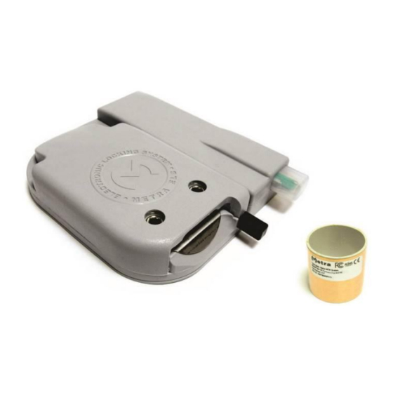
Electronic Lock RFID ISO MT Technical Manual Components Electronic Lock RFID ISO MT Base, strike and front cover Connection plates Cabling Lock position The lock position has to be identified before the process of wiring. General recommendation is that the lock should be positioned near to the handle, so the users are operating the locks as directly as possible. -
Page 6: Link 2 Connection Plates
Electronic Lock RFID ISO MT Technical Manual Contact Metra to help you find the best solution for wiring, Electronic Lock RFID and MEW Controller position, prefabricated wires and other mounting accessories and options. Link 2 connection plates Wiring schematic example using “Link 2” connection plates. Link 2 connection plates are used where there full height lockers. -
Page 7: Link 4 Connection Plates
Electronic Lock RFID ISO MT Technical Manual Link 4 connection plates Wiring schematic example using “Link 4” connection plates. Link 4 connection plates are used where there are single or double lockers in a column. Schematic bellow shows one sided bank of lockers with 4 lockers per locker block. -
Page 8: Link 8 Connection Plates
Electronic Lock RFID ISO MT Technical Manual Link 8 connection plates Wiring schematic example using “Link 8” connection plates. Link 8 connection plates are used where there are multiple lockers in a column. Schematic bellow shows one sided bank of lockers with 16 lockers per locker block. -
Page 9: Crimping The Connectors
Electronic Lock RFID ISO MT Technical Manual Crimping the connectors Six-pole flat cable connectors Tools required: To crimp the connectors you need crimpers for IDC connectors (left) or Metra special connector crimper with charger (bottom) (both can be purchased from Metra on request) and a sharp knife or OLFA cutter. - Page 10 Electronic Lock RFID ISO MT Technical Manual STEP 2: Place the connector on the cable so that marker is on the red wire. There are two possible ways to do it, so mind also the orientation of the leading dent. To achieve a good quality contact on all wires, the connector should be perpendicular to the cable and the end of the cable should be overhanging the connector for a few mm.
-
Page 11: Three-Pole Easywire Cable Connectors
Electronic Lock RFID ISO MT Technical Manual STEP 7 (OPTION A): Placing the cable under the lock. Twist the 6-wire cable in the rabbet at the back side of the lock as shown on the picture (two options – depends of the cabling). STEP 7 (OPTION B): Placing the cable under the lock. - Page 12 Electronic Lock RFID ISO MT Technical Manual STEP 1: Separate approximately 4 centimetres of wires on a 3 pole 0.75mm cable. STEP 2: Place the connector in the pillars as shown on the photo. NOTE: Each pin on the connector is marked with a number from 1 to 3.
-
Page 13: Adjusting The Ejector Spring Force
Electronic Lock RFID ISO MT Technical Manual STEP 4: Repeat the same procedure on the other side and/or in the middle of the cable. Photo shows a middle connector. Middle connectors can be put in the middle or at the ends of the cable. STEP 5: You should end up with two or more connectors on a cable. -
Page 14: Mounting The Lock
Electronic Lock RFID ISO MT Technical Manual NOTE Do not over-compress the spring (force ejector inside the lock), as you might damage the switch! Spring force Ejector Screw A Screw B Weak Compressed Compressed Normal Extended ... - Page 15 Electronic Lock RFID ISO MT Technical Manual – Lock tip is even with the – Lock tip is over the inner WRONG! – Lock tip is behind inner plane of the door. The plane of the door. The door will the inner plane of the door and door will reach the lock tip.
-
Page 16: Procedure
Electronic Lock RFID ISO MT Technical Manual NOTE If the edge of the locker door is not overlapping the inner edge of the locker compartment for at least 6 millimetres a spacer for the lock is required. As a spacer different solutions are possible. Spacer can also be used to hide the connection cable. -
Page 17: Mounting The Strike
Electronic Lock RFID ISO MT Technical Manual STEP 2: Fix the lock in place with 4 screws. NOTE: Screws are not supplied by Metra. Mounting the strike STEP 1: Mounting holes for door strike should be predrilled in factory according to the specifications in appendices. - Page 18 Electronic Lock RFID ISO MT Technical Manual STEP 2: For easier mounting first stick the plastic cover over the metal pin to the plastic base as shown. STEP 3: First fix the strike with two screws. Use supplied washers between the screw and plastic strike body. Then fix the front cover including the antenna and the protective plastic.
-
Page 19: Final Operational Test Of The Locker
Electronic Lock RFID ISO MT Technical Manual Place Metra mounting jig on the loop and firmly close the door to position the strike and then tighten the screws. Do not over-tight the screws, the wire loop should still move freely. Remove the mounting jig. CORRECTLY TIGHT SCREWS Try moving the Wire loop left and right in the screws are correctly tightened, the wire loop should be able to... -
Page 20: Electronic Lock Set-Up
Electronic Lock RFID ISO MT Technical Manual Final check of the locker and mounting should be done after the lock is operational – connected to the driving or test unit. CHECK 1: Press the ejector to check the operation. The motor should operate swiftly. -
Page 21: Rfid Reader Test
Electronic Lock RFID ISO MT Technical Manual NOTE: Lockers must be unlocked before you start the indexing procedure. To open all lockers press the emergency open button. STEP 1: To index all Electronic Locks RFID connected to the device start by Electronic Lock RFID with the lowest locker number and rapidly press the plunger 3 times. -
Page 22: Maintenance Of The Lock
Electronic Lock RFID ISO MT Technical Manual STEP 1: To test the RFID reader close the locker door and hold them closed. Electronic Lock RFID starts to blink red. STEP 3: Present the RFID media. When the RFID media is in the antenna field, the Electronic Lock RFID will start blinking green. - Page 23 Electronic Lock RFID ISO MT Appendix 1 Dimensions 20±0.2 For M4 or smaller screws 18±0.2 For M5 or M6 screws 22.5 22.5...
Need help?
Do you have a question about the 114 and is the answer not in the manual?
Questions and answers