Table of Contents
Advertisement
Quick Links
Advertisement
Table of Contents

Summary of Contents for MYOSWISS The Myosuit
- Page 1 MYOSWISS AG User Manual The Myosuit...
- Page 2 FOR USE WITH MYOSUIT BATTERY REF: 1910002 MyoSwiss AG Hardturmstrasse 135 CH-8005 https://myo.swiss info@myoswiss.com Document version: 3.8 Release date: March 24 , 2020 This user manual is subject to periodic reviews, updates, and revisions. © Copyright 2020 MyoSwiss AG. All rights reserved.
-
Page 3: Table Of Contents
Safety ............................6 Operator responsibility ....................... 6 How to use this documentation ....................6 Symbols used in this manual ...................... 7 Symbols used in the Myosuit ...................... 7 Applicable classifications ......................8 Indications for use ........................ 9 Indications ..........................9 Contraindications ........................ - Page 4 Navigating in a training screen ................... 40 Navigating between training screens ................. 41 Changing the assistance and calibration levels ..............42 Calibrating the Myosuit for walking and stair negotiation ............ 42 Standing up from a chair ....................... 42 5 .............................. 43 Maintenance, battery care, cleaning, and storing the Myosuit .........
-
Page 5: Introduction
Figure I. Working principle of the Myosuit. The tension of an external tendon—routed behind the hip joint and in front of the knee joint—is regulated actively to assist the user with the extension of both joints. -
Page 6: Important Information
Myosuit. Proper training by MyoSwiss-approved personnel must be carried out with each person involved in the operation of the Myosuit. The operator is responsible for guiding the user through the operation of the Myosuit and to ensure, to the best of his or her abilities, the safety of the user while using the Myosuit. -
Page 7: Symbols Used In This Manual
Symbols used in this manual Symbol Meaning of the symbol Caution. Please consult the safety instructions. General warning and safety notices. General information, tips, and comments about operating the Myosuit. Symbols used in the Myosuit Symbol Meaning of the symbol Caution... -
Page 8: Applicable Classifications
M Y O S U I T – U S E R M A N U A L Symbol Meaning of the symbol Do not store the battery when discharged Keep dry Use only the charger provided for the battery Medical device Reference number Lot number... -
Page 9: Indications For Use
M Y O S U I T – U S E R M A N U A L 3. Indications for use Users with unilateral or bilateral lower limb paresis, or flaccid paralysis, or muscle weakness due to neurological and neuromuscular disorders e.g. multiple sclerosis, muscle dystrophy, stroke; trauma i.e. incomplete spinal cord injury;... -
Page 10: Safety Regulations
U S E R M A N U A L 4. Safety regulations Do not use the Myosuit prior to reading and understanding this manual. Do not conduct training with the Myosuit if the harness and/or knee orthoses do not fit the user properly. -
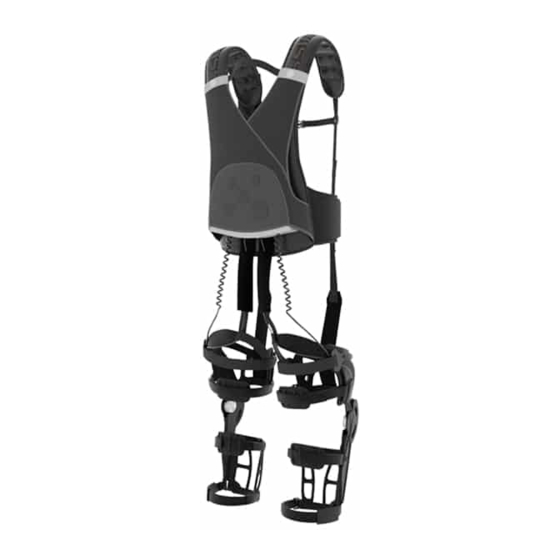
Page 11: Myosuit Components
– U S E R M A N U A L 5. Myosuit components Figure 5.1. The Myosuit and its components Functions of the Myosuit components Component Function The remote control is the main interface to control the functions of Remote control the Myosuit. -
Page 12: Operation Modes
U S E R M A N U A L Component Function The harness holds the actuation unit and battery of the Myosuit. It Harness attaches to the user using the shoulder straps, hip belt, and sternum strap. The knee orthoses help to route the forces from the actuation unit along the user’s legs. - Page 13 In this mode, the tension of the tendons is kept to a minimal. The motors in the actuation unit are audible in this mode. In this mode, the tension of the Myosuit tendons is kept constant. The tension Isometric force mode can be adjusted between six levels of tension.
-
Page 14: Remote Control
U S E R M A N U A L Part Remote control The remote control is the main interface to control the functions of the Myosuit. Remote control functions Remote control button layout Figure 2.1.1 Remote control and its components... -
Page 15: Functions Of The Components Of The Remote Control
Light indicator Myosuit. The standby button is used to power the Myosuit ON and OFF. When the Myosuit is OFF, a short press of the standby button turns the Standby button Myosuit ON. When the Myosuit is ON, a long press of the standby button turns the Myosuit OFF. -
Page 16: Configuration Screens
U S E R M A N U A L Configuration screens Detailed information on how to operate the Myosuit is provided in Part 2 of this user manual. The following screen samples are shown for general reference. Figure 2.1.2 Configuration screens Training screens Figure 2.1.3. -
Page 17: Actuation Unit
Functions of the actuation unit components Component Function Battery The battery provides the energy needed to power the Myosuit. The battery release button helps connect and disconnect the battery from the Battery release button actuation unit. Page 17 of 53... - Page 18 In case of an emergency during operation, the battery can be quickly released using the battery release button. This will turn off the Myosuit immediately. The cooling vents should not be blocked when the Myosuit is being used. This Cooling vents may cause the Myosuit to overheat.
-
Page 19: Harness
U S E R M A N U A L Harness The harness holds the actuation unit and battery of the Myosuit. It attaches to the user using the shoulder straps, hip belt, and sternum strap. Components of the harness Figure 2.3.1. - Page 20 M Y O S U I T – U S E R M A N U A L Component Function Harness cover and The harness includes a textile cover that protects the actuation unit. The cover attachment has two attachment points that connect the cover to the shoulder straps. The shoulder strap attachment connects the shoulder strap to the inner hip Shoulder strap attachment belt via a plastic hook.
-
Page 21: Knee Orthoses
M Y O S U I T – U S E R M A N U A L Knee orthoses The knee orthosis routes the forces from the actuation unit along each leg. Components of the knee orthoses Figure 2.4.1 Knee orthosis Functions of the components of the knee orthoses Component Function... - Page 22 The padding on the proximal side of the shank frame provides added comfort padding for the user. It should always be used when the Myosuit is in use. Shank frame – distal The padding on the distal side of the shank frame provides added comfort 4.10...
-
Page 23: Passive Elements
M Y O S U I T – U S E R M A N U A L Passive elements The passive elements are elastic elements that support the flexion movements of the hip, knee, and ankle. Components of the passive elements Figure 2.5.1 Passive elements. - Page 24 M Y O S U I T – U S E R M A N U A L Component Function The ankle ligament assists the user with dorsiflexion of the ankle joint. Ankle ligament Its use is recommended for those users with weakness of the ankle dorsiflexor (dorsiflexor) muscles or hip flexors, or who may have issues with clearing the ground while walking.
-
Page 25: Force Routing Sleeves
M Y O S U I T – U S E R M A N U A L Force routing sleeves The force routing sleeve routes the tendons along the back side of the user’s leg. Components of the force routing sleeve Figure 2.6.1 Force routing sleeves Functions of the components of the force routing sleeves... -
Page 26: Donning The Myosuit
Preparing for the first training session For patients training with the Myosuit for the first time, the operator should explain to the patient the general working of the Myosuit. Users should be made aware of the benefits and risks of training with the Myosuit. -
Page 27: Defining The Location Of The Shoulder Straps And Hip Ligaments
During the donning procedure, the operator needs to follow a series of steps to 1) prepare, 2) attach, and 3) adjust the Myosuit to the user. The Myosuit includes two different colors to help the operator identify the elements for preparation, attachment, or adjustment. -
Page 28: Myosuit Preparation
Wear comfortable shoes. If the user needs assistance from the ankle ligament, the user should wear shoes with laces. Prior to donning the Myosuit, please prepare the system for the user by performing the following steps. The sizes are available for review in the user’s profile. -
Page 29: Donning The Myosuit
Donning the Myosuit The Myosuit can be donned while the user is either standing or sitting. The pictures below shoe the donning procedure being done on a user that is standing. The same steps should be taken if the user is sitting. - Page 30 7. (Optional) Tighten the hip ligaments. 8. The Myosuit should sit comfortably for the user. As a final check, ask the user if there are any straps that feel uncomfortable (Figure 3.1.4). The shoulder straps should sit comfortable and not apply much pressure to the user’s shoulders.
- Page 31 M Y O S U I T – U S E R M A N U A L Figure 3.1.4. Steps to don the Myosuit. The donning process can be done while the patient is either standing or sitting. Page 31 of 53...
-
Page 32: Final Adjustments
Not adjusting this strap properly can lead to poor performance from the Myosuit and potential discomfort for the user. Figure 3.1.6. Adjustment of the proximal strap of the thigh. The height of the triangle made between the strap and the force routing element should not exceed the height of two fingers. -
Page 33: Doffing The Myosuit
The doffing procedure can be done while the user is either sitting or standing. The steps are as follow: 1. Turn off the Myosuit by pressing the standby button for 5 seconds. A screen to confirm the powering off of the Myosuit will show. The operator can then cancel or confirm the powering off. The Myosuit can be turned off in any state of operation. -
Page 34: Using The Myosuit
The Myosuit will then perform an internal system check. During the internal check, the remote control screen will show the Myosuit logo on the top left corner and the current version of the software on the bottom left corner (splash screen). -
Page 35: Turning Off The Myosuit
M A N U A L Figure 4.1.1 Turn on the Myosuit by a short press of the standby button (top left). The light indicator will turn blue and the splash screen will show up to show the Myosuit logo and current version of the software. -
Page 36: Configuring A Training Session
Once the Myosuit is turned on and the initialization is complete, the splash screen will disappear, and the operator is asked to select the operator that will be conducting the training session. To configure a training session, the operator should: 1. -
Page 37: Training With The Myosuit
Myosuit applies tension to the tendons. The operator should inform he user that small pull will happen. Figure 4.1.4. At the beginning of training, the Myosuit first calibrates its sensors. Once the calibration is done, it will automatically move on to the following screen. - Page 38 Description Symbol and color Transparency This mode sets the Myosuit to follow the movements of the user without assisting or hindering their movements—i.e. the Myosuit is transparent to the user. Transparency mode can be triggered from any of the three assistive modes.
-
Page 39: Training Screen Layout And Feedback To The Operator And User
M Y O S U I T – U S E R M A N U A L Training screen layout and feedback to the operator and user Figure 4.1.5 Layout of a training screen. Navigating the training screens To navigate in a training screen, use the navigation button to move, clockwise, between 5 fields available: 1) current training mode, 2) assistance level of the left leg, 3) calibration level of the right leg, 4) calibration level of the left leg, and 5) assistance level of the left leg. -
Page 40: Navigating In A Training Screen
M Y O S U I T – U S E R M A N U A L Navigating in a training screen Figure 4.1.6 Navigating within a training screen. Using the navigation button, short and long presses change between the fields in a clockwise (short press) and counterclockwise (long press) manner. -
Page 41: Navigating Between Training Screens
M Y O S U I T – U S E R M A N U A L Navigating between training screens To navigate between training modes, move the cursor to the current training mode and use the left and right arrow buttons to navigate between modes. -
Page 42: Changing The Assistance And Calibration Levels
Standing up from a chair To assist a user in standing up from a chair, the Myosuit first recognizes that the user is sitting and then assists as the user is standing up from the chair. It does this by detecting that the user’s upper body has leaned forward and then engages the sit-to-stand assistance. -
Page 43: Maintenance, Battery Care, Cleaning, And Storing The Myosuit
Myosuit as described below. Battery care Proper battery care must be done to ensure safe use of the Myosuit and maximum battery life. The batteries supplied with the Myosuit are specially designed for the Myosuit. Do not use other types of batteries. -
Page 44: Changing The Battery
M Y O S U I T – U S E R M A N U A L Changing the battery Figure 5.1.1 Disconnecting and connecting the battery To remove the battery, press the battery release button (2.2) and pull the battery away from the actuator unit. To connect the battery, slide the battery into the battery support rails (2.6) and push the battery into the actuator unit. -
Page 45: Cleaning
The sensor cables should not have any joints (i.e. connectors). If any part of the cable looks breached, please contact MyoSwiss. If you find any of these elements are torn or worn out, please contact MyoSwiss to replace them with new ones. Disposing of the Myosuit ... -
Page 46: Troubleshooting
Servicing or repairs must be performed only by MyoSwiss- approved personnel. Do not remove the cover from any components of the Myosuit. Information messages In the event of an alert, the remote control will beep and vibrate to call upon the user’s attention. A message will show on the remote control the reason for the issue. -
Page 47: Errors
The operator should write down the error code and inform MyoSwiss. In the case of minor issues, as those listed below, the operator can try to solve it according to the procedure provided. - Page 48 Motor driver left communication error Please contact Myoswiss if the error re-occurs. Turn off the Myosuit and wait for the motors to cool down. Motor right overheat Please contact Myoswiss if the error re-occurs. Turn off the Myosuit and wait for the motors to cool down.
- Page 49 Myosuit SD card is not inserted Please contact Myoswiss if the error re-occurs. Check that the Myosuit is running the latest software version. Incompatible SD card protocol Please contact Myoswiss if the error re-occurs.
-
Page 50: Reporting Undesirable Events
In the case that serious incidents that have led, or could have led, to serious injuries to persons and damage to objects, these events must be reported immediately to MyoSwiss AG and/or to the competent authority of the Member State in which the user is established. -
Page 51: Technical Data And Specifications
M Y O S U I T – U S E R M A N U A L Part Technical data and specifications The following values must be considered when operating the Myosuit Capacity Parameter Value range User maximum weight 110 kg User minimum height... -
Page 52: Storage Conditions
M Y O S U I T – U S E R M A N U A L Parameter Value range Environment atmospheric pressure 700 hPa to 1060 hPa IP22 – per 60601-1-11 Water resistance per IEC 60529:1989/AMD2:2013/COR1:2019 Storage conditions Parameter Value range Temperature... -
Page 53: Index
Index Action button ........15 Inner sleeve ........25 Actuation unit ........11 Isometric force mode ......13 Ankle ligament (dorsiflexor) ....24 Knee orthosis ........12 Ankle ligament hook ......24 Left arrow button ......15 Ankle ligament length adjustment ..24 Light indicator ........
Need help?
Do you have a question about the The Myosuit and is the answer not in the manual?
Questions and answers