
Summary of Contents for Romet AdEM-PTZ
- Page 1 A D V A N C E D E L E C T R O N I C M O D U L E P/N 17-MN-CA O P E R A T I N G M A N U A L May 2019 Rev.13...
-
Page 2: Table Of Contents
TABLE OF CONTENTS 1. INTRODUCTION TO AdEM®-PTZ Characteristic and What’s New How to Specify Model How it Works RometLink Software AdEM®-PTZ Typical Application 2. GETTING STARTED Keyboard Operation Scroll-button Operation Scroll Magnetic Sensor Operations Menu Structure 3. MODES OF OPERATION Normal Display Mode Custom Display Mode Full Display Mode... - Page 3 EM® ............... 69 MODULES INSTALLATION ON LMMA METERS EM® ..............70 MODULES INSTALLATION ON METERS EM® ....71 MODULES INSTALLATION ON METERS WITH ROMET BACKUP COUNTER UNIT ................72 LECTRONIC ETER OUNTING OSITIONS EM®-PTZ A – – ..........73 UDIT...
-
Page 4: Introduction To Adem®-Ptz
NX-19 or AGA8 or SGERG88 formula (see Correction Equation for details). Romet combines the power of its field proven gas measurement technology and integration of computer-based software to come with the product AdEM®-PTZ. -
Page 5: How To Specify Model
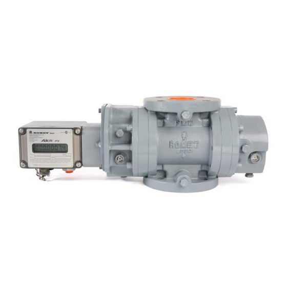
The AdEM®-PTZ is a solid-state electronic volume conversion module that is directly coupled to the magnetic housing of the Romet meter body. The AdEM®-PTZ employs a magnetic sensing device to sense the rotation of the meter’s outer magnet which produces a high-resolution input that represents the non-converted (UNC - uncorrected) metered gas volume. -
Page 6: Rometlink Software
In addition to compensating for live pressure and temperature conditions, the AdEM®-PTZ has a low flow volumetric linearization feature that enhances the rangeability of the Romet meter to 200:1 or better with an error of less than 1.0%. This feature, if activated, is automatically initiated at flow rates below 10% of the Qmax rating for the meter. - Page 7 Help files and Intervals Log window below for details (Fig.6). Fig.6 Interval Log window WARNING! WHEN CHANGING INTERVAL ITEMS, OLD AUDIT TRAIL WILL BE DELETED AND CLEARED. DOWNLOADING OF AUDIT TRAIL MUST BE DONE BEFORE CHANGING AUDIT TRAIL CONFIGURATION IN ORDER TO SAVE PREVIOUS DATA. ROMET LTD.
- Page 8 Fig.8 Event Log window ✓ ALARM Log: 102 alarm events. See RometLink Help files and Alarms Log window below for details (Fig.9). Fig.9 Alarm Log window For more details of software functions, please refer to online help. ROMET LTD.
-
Page 9: Adem®-Ptz Typical Application
AdEM®-PTZ can be used in a variety of ways. It can be used as a stand-alone device which can be configured or evaluated by portable keyboard. For ease of operation and advance functions, it is recommended to use Romet RometLink communication software either through using direct cable connection to the computer (RS232 or RS485), or remotely by using a Hayes compatible modem connection (including wireless modem). -
Page 10: Getting Started
AdEM®-PTZ is usually supplied fully calibrated/preprogrammed and mounted to pressure body as per specifications of each customer. The AdEM®-PTZ modules can be supplied for Romet pressure bodies as well as other manufacturers’ pressure bodies. The module, when removed from the box, will be in Normal Display mode only. -
Page 11: Scroll-Button Operation
As an option to Scroll Button (SB) can be used Scroll Magnetic Sensor installed inside of enclosure, therefore invisible to public. Sensor is activated by dedicated magnetic tool eg. magnetic pen, screwdriver or other. Magnet Fig.10 AdEM with hidden magnetic sensor as Scroll Button ROMET LTD. -
Page 12: Operations Menu Structure
AdEM™-PTZ AdEM®-PTZ Operation Menu Structure ROMET LTD. -
Page 13: Modes Of Operation
AdEM®-PTZ will revert to the Normal Display Mode after approximately 60 seconds if no buttons are pressed. The Custom Display menu is configurable in the Set Up Mode (refer to Section 5, Set Up) Configuration of this mode is protected by Password. Password or Program Switch protection does not apply to access this mode. ROMET LTD. -
Page 14: Full Display Mode
Display until communication is finished. If by any occasion communication between AdEM®-PTZ and computer/modem is broken, corrector will revert to Normal Mode after timeout. Access by keyboard and Scroll-Button is disabled under Communication Mode. Input Pulse collection and processing, Volume Index updates and Output Pulse generation continues as normal. ROMET LTD. -
Page 15: Security
To enter software: • Default password for limited level user is: 55555. • Default password for standard Administrator level user is: ROMET. • Default password for Service level user is: SERVICE. • Default password for full Administrator/ Superuser level: available for Authorized users only. -
Page 16: Program Switch Jumper
“LOG ON” password, please refer to “README” file on CD or the “RometLink software password and module access code” document. Program Switch (Jumper) To protect the AdEM-PTZ module from unwanted changes to Metrological parameters, there are two options. ROMET LTD. - Page 17 Access with Password TESTING MANU: Access with password Sensor Convert ✓ From Software for firmware versions prior to D02: GAS DAY START TIME PRESSURE HIGH LIMIT PRESSURE LOW LIMIT TEMP HIGH LIMIT TEMP LOW LIMIT UNC FLOW HIGH LIMIT ROMET LTD.
-
Page 18: How To Enable/Disable Program Switch
These parameters can be configured by RometLink software only. Refer to Measurement Canada document S-EG-06 for Event Logger Type A (self-contained Event logger) information. ✓ See Table 1 – Romet products Standard Setup Parameters for parameters monitored by Event Logger overall and protected by Event Logger type A. -
Page 19: Event Logger Type A
Care should be taken to not damage the cables. If AdEM-PTZ was metrological sealed, the seal must be broken to perform the Program Switch service. Procedure to “Enable” Program Switch disabled by Jumper: 1. Remove the seal screws and switch protector plate if installed. - Page 20 AdEM™-PTZ Table 1. Event Logger Parameters. Parameters marked CFG are configurable, registered in Event Logger Type A, while Program Switch is set “Disable”. ROMET LTD.
-
Page 21: Set Up
The AdEM®-PTZ module would normally be shipped from Romet with the Setup configuration fully programmed to a customer's specifications. The exception would be an order for a loose AdEM®-PTZ module where the customer may not have specified the meter type. In such an instance, the meter type and some of the associated parameters would need to be programmed by the customer during the installation of the AdEM®-PTZ module to the meter body. -
Page 22: Set Up - Flowchart
AdEM™-PTZ ROMET LTD. - Page 23 AdEM™-PTZ ROMET LTD.
- Page 24 AdEM™-PTZ ROMET LTD.
- Page 25 AdEM™-PTZ ROMET LTD.
- Page 26 AdEM™-PTZ ROMET LTD.
- Page 27 AdEM™-PTZ ROMET LTD.
-
Page 28: Setup By Software
AdEM™-PTZ Setup by Software Most of Setup parameters can be change only by software, contrary to most of previous Romet products where complete Setup was fully or almost fully available through keyboard operation. Under RometLink’s Talk to Unit/Setup drop down menu, there are available the following options: ✓... - Page 29 AdEM™-PTZ Table 2 – Romet Products Standard Setup Parameters Product Parameter Name Description Authorization AdEM-T AdEM-PTZ AdEM-S ElogA AGA-8 Molar List AGA-8 Molar List 21 Items Read Only after Sealing/ ELogA √ √ √ Alarm Output Alarm Output Read Only...
- Page 30 AdEM™-PTZ Product Parameter Name Description Authorization AdEM-T AdEM-PTZ AdEM-S √ Interval Field 10 Selectable Interval Field 10 Read/Write √ Interval Field 5 Selectable Interval Field 5 Read/Write √ Interval Field 6 Selectable Interval Field 6 Read/Write √ Interval Field 7...
- Page 31 AdEM™-PTZ Product Parameter Name Description Authorization AdEM-T AdEM-PTZ AdEM-S √ Pressure Factor Pressure Factor Live Read Only Pressure Factor Type Pressure Factor Type Read Only after Sealing/ElogSW ElogSW √ Pressure High Alarm: Pressure High Read Only √ Pressure High Limit...
-
Page 32: Calibration
If calibration is aborted due to any reason, the unit will revert to old saved data that is still valid. Calibration by Keypad The flowchart below shows how to calibrate Gas Temperature sensor. Gas temperature Calibration by Keyboard - Flowchart ROMET LTD. - Page 33 Calibration and Setup Modes. Calibration by software Temperature calibration by RometLink software is fully available under Calibrate Unit/1-Point Gas Temperature. See Fig.14 for 1-Point Temperature Calibrate windows. Refer to RometLink Help for further calibration details. Fig.14 Software 1-Point Temperature Calibrate Window ROMET LTD.
-
Page 34: Ambient Temperature Calibration
In order to perform calibration, the Program Switch on the Main Board must be moved to the “Enable” position (refer to section 4, SECURITY). Connect the pressure supply to the unit. Check for any leakage. If confirmed OK, set the pressure controller to the LOW pressure point (approximately 20% of the range). ROMET LTD. - Page 35 Point Gas Pressure…. Once Calibration window is open (see Fig. 16, 3-Point Gas Pressure Calibrate window), after stabilizing of A/D counts enter True Pressure (value displayed by the pressure controller) for LOW pressure point, then select Low Point from Capture As: selection. Repeat sequence for MIDDLE and HIGH pressure points. ROMET LTD.
- Page 36 Selection of pressure Calibration points Usually pressure points are established as: 20% (Low Point), 60% (Middle Point), 100% (High Point), of full pressure range. However, points can be chosen differently if needed (e.g. for very low-pressure ranges of AdEM®-PTZ) ROMET LTD.
- Page 37 Presently Absolute option is approved for Canada. Once 1-point pressure calibration is used, future 3-point calibration must be performed by Software to automatically cancel 1-point calibration. Cancelation is necessary for correct performance of 3-points calibration by Keypad. ROMET LTD.
-
Page 38: Proving
AdEM®-PTZ (5 ms pulse width). Model 5 Prover A Romet cable assembly (Romet P/N 34-097-40) is required to connect the unconverted (UNC VOL) pulse output (6 pin Cannon) of the AdEM®-PTZ to the Model 5 Prover. Other cable assemblies are available to accommodate different pin arrangements and other connector types. - Page 39 1. Install the appropriately sized flange connections on the prover hose 2. Connect the hose assembly to the meter flanges with a gasket to ensure an air tight fit 3. Connect the AdEM®-PTZ to the interface box on the prover with the appropriate Romet cable connector assembly.
-
Page 40: Testing
During a test the total conversion factor for the AdEM®-PTZ is calculated live from measured values of pressure and temperature references. ROMET LTD. - Page 41 - base absolute pressure (10.00 to 16.00 psi, 0.70000 to 1.10000 bar, 70.000 to 110.000 kPa) base - base temperature (32°F to 86°F, 0°C to 30°C) base - flowing gas absolute pressure - flowing gas temperature Hs - gas calorific value (combustion heat) d - specific gravity ROMET LTD.
-
Page 42: Ptz Conversion Test Steps
It is recommended that two to three pressure and temperature values across the operating range of the sensors are verified. In the event, that a sensor is found have a significant error (> 0.5%), refer to Section 6, CALIBRATION. ROMET LTD. -
Page 43: Testing Output Pulse Using Pushbutton
Switch. It can be factory disabled. To test output pulse, the following procedure needs to be performed: ▪ Press and hold pushbutton for about 8 seconds until LCD shows “OUTPUT” ▪ Upon “OUTPUT” release pushbutton promptly ▪ Pulses are automatically generated ROMET LTD. -
Page 44: Alarms And Malfunctions
Clearing P or T malfunction(s) automatically clears value stored in parameter " . The value of this parameter is shown in the FULL DISPLAY mode and must be recorded before clearing a malfunction. The value can also be retrieved from Event Logger that is read by software. ROMET LTD. -
Page 45: Limit Violation Monitoring/Alarms
Tools needed for installing a new battery: Cutter and Pliers. Battery and two-wire splice connector can be obtained from Romet; P/N 46-092-40 and 2019. Limit Violation Monitoring/Alarms AdEM®-PTZ firmware has been designed to monitor the set-point limit (except Low Battery) violations of the following parameters: •... - Page 46 PTZ and AdEM®-PTZ BARRIERS INSTALLATION FOR CONNECTORS for Intrinsically safe connections arrangements to the AdEM®-PTZ. Romet’s standard 6 pin Cannon connector with 6 ft cable and ferrule ends is P/N # 43-035-40 and is available for ordering (other connections available).
- Page 47 Pre 1994 Romet TC Meter Body design (with a TEMPERATURE WELL) The AdEM®-PTZ can be installed on any Romet TC meter body design that has been manufactured before 1994 (the first two digits of the Romet meter serial number signify the year of manufacture, e.g. SN#931234 was manufactured in 1993).
- Page 48 G1000/RM1600 are only available as a STD pressure body design (without a TEMPERATURE WELL). Installation to Romet RMT Meters The AdEM PTZ module can be installed on the Romet RMT Meters using standard Romet adaptor kit as for RM and G series.
- Page 49 Servicing should be carried out by authorized personnel only. Contact supplier for more information about servicing, including sensors replacement procedures and conditions. Access to temperature and pressure sensors is restricted. After servicing sensors, sealing procedure must be performed (if required) by authorized person. ROMET LTD.
- Page 50 • Standard pulse width: changeable from 5 to 50ms by • Supercompressibility (live or fixed) 5ms step with addition of 65, 120, 125, 250, 500ms, • Low flow compensation if applicable (Romet meters all with selectable pulse spacing: OFF ,50ms, 100ms, only) expands meter rangeability to 200:1...
- Page 51 AdEM™-PTZ RS232 Communication Mounting • ROMET Link software to take full advantage of • Romet, LMMA or B3 TC pressure body • Option to mount to Romet standard pressure body RS232 or RS485 port (Windows based) • Direct connection or link through modem using an external temperature probe •...
- Page 52 EM® ............... 69 MODULES INSTALLATION ON LMMA METERS EM® ..............70 MODULES INSTALLATION ON METERS EM® ....71 MODULES INSTALLATION ON METERS WITH ROMET BACKUP COUNTER UNIT ................72 LECTRONIC ETER OUNTING OSITIONS EM®-PTZ A – – ..........73 UDIT...
- Page 53 AdEM®-PTZ ROMET LTD.
- Page 54 AdEM®-PTZ ROMET LTD.
- Page 55 AdEM®-PTZ ROMET LTD.
- Page 56 AdEM®-PTZ ROMET LTD.
-
Page 57: Adem-Ptz Modbus 16 Bit Standard
AdEM®-PTZ AdEM-PTZ MODBUS 16 BIT STANDARD REGISTERS MAPPING NOTE: The firmware supports single and Multi-register (Maximum 21) reading. The registers addresses are fixed, can not be changed. Contact manufacturer if needs further information regarding protocol details ROMET LTD. -
Page 58: Bit Romet Modbus
AdEM®-PTZ 32BIT ROMET MODBUS ROMET LTD. - Page 59 AdEM®-PTZ ROMET LTD.
- Page 60 AdEM®-PTZ Note that some parameters and data are not available for AdEM PTZ Contact manufacturer if needs further information regarding protocol details ROMET LTD.
-
Page 61: Adem- Ptz Nameplates
AdEM®-PTZ AdEM- PTZ Nameplates 49-100-6C Nameplate for Metric and Imperial configuration 49-100-6GC Nameplate for Imperial configuration only (in Canada) ROMET LTD. -
Page 62: A Dem®-Ptz Pulse Output Connections
AdEM®-PTZ ROMET LTD. -
Page 63: A Dem®-Ptz Pulse Output Connections - Pigtail Options
AdEM®-PTZ PULSE OUTPUT CONNECTIONS - PIGTAIL OPTIONS ROMET LTD. -
Page 64: Adem®-Ptz Installation With Barriers For Hazardous Location
AdEM®-PTZ AdEM®-PTZ INSTALLATION WITH BARRIERS FOR HAZARDOUS LOCATION ROMET LTD. -
Page 65: A Dem®-Ptz Installation With Barriers -Isolators For Hazardous Location
AdEM®-PTZ AdEM®-PTZ INSTALLATION WITH BARRIERS - ISOLATORS FOR HAZARDOUS LOCATION ROMET LTD. -
Page 66: A Dem®-Ptz To Pc (Direct ) Communication Cables
AdEM®-PTZ ROMET LTD. -
Page 67: A Dem®-Ptz To Modem Standard Communication Cables
AdEM®-PTZ ROMET LTD. - Page 68 AdEM®-PTZ ROMET LTD.
-
Page 69: A Dem®-Ptz General Dimensions
AdEM®-PTZ ROMET LTD. -
Page 70: Typical Pressure Kit Installation
AdEM®-PTZ ROMET LTD. -
Page 71: Adem Modules Installation On Romet Meters
AdEM®-PTZ AdEM Modules Installation on Romet Meters For Vertically Mounted Romet Meters: Use Mounting Plate P/N 46-100-3 For Horizontally Mounted Romet Meters: Use Mounting Plate P/N 46-100-3 ROMET LTD. -
Page 72: Adem Modules Installation On Lmma Meters
AdEM®-PTZ AdEM Modules Installation on LMMA Meters For Vertically Mounted LMMA 2M to 5M Meters: Use Mounting Plate P/N 46-100-13 For Horizontally Mounted LMMA 2M to 5M Meters: Use Mounting Plate P/N 46-100-13 ROMET LTD. -
Page 73: Adem Modules Installation On B3 Meters
AdEM®-PTZ AdEM Modules Installation on B3 Meters For Vertically Mounted B3 Meters: Use Mounting Plate P/N 46-150-11 Orientation mark For Horizontally Mounted B3Meters: Orientation mark Use Mounting Plate P/N 46-150-11 ROMET LTD. -
Page 74: Adem Modules Installation On B3 Meters With Romet Backup Counter Unit
AdEM®-PTZ AdEM Modules Installation on B3 Meters with Romet Backup Counter Unit Explored View of Installation B3 Meter with Installed AdEM PTZ with Backup Counter Unit ROMET LTD. -
Page 75: Electronic Meter Mounting Positions
AdEM®-PTZ ROMET LTD. -
Page 76: Adem®-Ptz Audit Trail - Variable Intervals - Explanation
11. Max Temperature 12. Max Temperature Time 13. Min Temperature 14. Min Temperature Time 15. Average Pressure 16. Max Pressure 17. Max Pressure Time 18. Min Pressure 19. Min Pressure Time 20. Average Total Factor 21. Average Battery Voltage ROMET LTD. - Page 77 11. Max Temperature 12. Max Temperature Time 13. Min Temperature 14. Min Temperature Time 15. Average Pressure 16. Max Pressure 17. Max Pressure Time 18. Min Pressure 19. Min Pressure Time 20. Average Total Factor 21. Average Battery Voltage ROMET LTD.
- Page 78 Trial must be done before changing audit trial configuration in order to save previous data. These items are configured in setup by software only under “Interval Type”: “Interval Field 5” “Interval Field 6” “Interval Field 7” “Interval Field 8” “Interval Field 9” “Interval Field 10” ROMET LTD.
-
Page 79: Adem®-Ptz Daily Log Explanation
6. Daily Average Temperature 7. Daily Average Total Factor 8. Daily Average Battery Voltage Note: These items are saved daily at specific time configured in setup by software only, named “Gas Day Start Time”. Note: Capacity is 1024 days of storage. ROMET LTD. -
Page 80: Adem®-Ptz Allowable Range Of Application For Some Parameters
Allowable index and output pulses for AdEM®-PTZ Imperial (cf) Metric (m³) Index: 0.01, 1, 10, 100, 1000, 10000 Index: 0.0001, 0.01, 0.10, 1.00, 10.00, 100.00 Output: 1, 10, 100, 1000, 10000 Output: 0.01, 0.10, 1.00, 10.00, 100.00 Note: Output cannot be less than Input. ROMET LTD. -
Page 81: Adem®-Ptz Custom Display Configuration Options
“Customer Display 3” “Customer Display 4” “Customer Display 5” “Customer Display 6” “Customer Display 7” “Customer Display 8” “Customer Display 9” “Customer Display 10” “Customer Display 11” “Customer Display 12” “Customer Display 13” “Customer Display 14” “Customer Display 15” ROMET LTD. -
Page 82: Meter Selection And Application
AdEM®-PTZ METER SELECTION AND APPLICATION ROMET offers a variety of measuring instruments to meet the diverse requirements posed by the natural gas industry. The following guidelines are offered to assist in the selection of a suitable mechanical or electronic measuring device for a specific gas application. - Page 83 The TCID meter may also be used as a mechanical temperature back-up system when paired up to an electronic temperature/pressure recorder or volume corrector. TCID-RM11000 ROMET LTD.
-
Page 84: Electronic Meter/Instrument Types
200:1 or better, with an error of less than ± 1.0%. This new compact design module offers up to 20 years battery life in a service-free, weather resistant enclosure. This device has fully developed one-way communication features using RometLink computer software. ROMET LTD. - Page 85 This new compact design module offers 10 to 20 years battery life in most applications in a service-free, weather resistant enclosure. This device has fully developed one-way communication features using RometLink computer software or Implemented Modbus RTU protocol that makes this device available for other communication and control systems, e.g.: SCADA. ROMET LTD.
- Page 86 Romet Limited reserves the right to change any information in this manual without notice. All of the information and data in this manual has been carefully compiled and thoroughly checked. However, Romet Limited will not assume responsibility for any possible errors or omissions. ROMET and ROMET & DESIGN are registered trademarks of...
Need help?
Do you have a question about the AdEM-PTZ and is the answer not in the manual?
Questions and answers