
Subscribe to Our Youtube Channel
Related Manuals for Vimar Eikon 20470

Summary of Contents for Vimar Eikon 20470
- Page 1 Installer manual Eikon 20470 Idea 16470 Plana 14470 Access control and appliance management via BUS using a transponder card or key HOME AUTOMATION...
-
Page 3: Table Of Contents
CONTENTS 1. Legend ..................................2. Installing the system via BUS ............................3. Main features and functions of the system components ....................3.1 - Transponder key reader ............................3.2 - Transponder card and key ............................ 3.3 - Relay actuator ..............................3.4 - Power supply unit ..............................4. -
Page 4: Legend
1. Legend Operations to be performed solely LED blinking green green by skilled personnel amber LED blinking amber Operations that can be performed also by the user LED blinking red LED blinking red-off-green LED off green LED on green green LED blinking red-green green LED on red... -
Page 5: Installing The System Via Bus
• For the connections use the twisted pair and sheathed ca- • Maximum bus cable length with 2 power supply units: 500 ble VIMAR 01840.E (2 x 0.5 mm ). The wire pair distributes m. For optimum load distribution, it is necessary to connect both the power supply voltage (29 V d.c.) and the device... - Page 6 120-230 V~ 50-60 Hz 29 V d.c. A possible second power supply unit 120-230 V~ 50-60 Hz 29 V d.c.
-
Page 7: Main Features And Functions Of The System Components
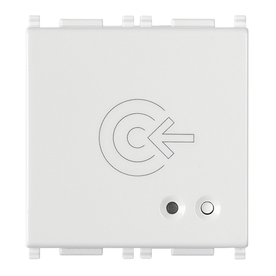
• Transponder reader • Antitamper (not active). This feature can only be used when • Typical consumption: 22 mA there is integration with the Vimar intrusion detection alarm • Operating temperature: –5°C - +45°C. system. • Command for enlisting the relay (procedure that is activated when there is an enabling key and by pressing the button on the front). -
Page 8: Transponder Card And Key
Area Writable area for transmitter transponder card personalisation 01815 Key: +, - : Connection to BUS 01816 - 01816.H (front) Writable areas for specifying the name of the smart card holder and the addresses used Rear of the smart card personalised on request 01816 01816.H... - Page 9 tion of the arrow - figures 3.2a and 3.2b for the key; figures 3.2c and 3.2d for the card) with the connector, which is rec- ognized and signalled to the system. The keys and cards can have a MASTER or SLAVE function. The MASTER function enables opening the enabled accesses and performing read- 3.2c er management and maintenance operations.
-
Page 10: Relay Actuator
3.3 - Relay actuator • Indicator LED: - LED on red: in configuration phase The actuator is a device that, thanks to the potential-free - LED on green: relay activated contacts of the relay with which it is provided, is able to con- trol electric locks, activate the lighting circuit, etc. -
Page 11: Power Supply Unit
Technical characteristics 3.4 - Power supply unit • Power: 230 V~ 50/60 Hz The power supply unit enables obtaining a voltage of 29 V • Consumption: 150 mA d.c. for powering the system via BUS. • Dissipated power: 4 W 01400: Power unit with decoupling coil. -
Page 12: Operation
4. Operation 4.1 Initializing the transponder reader and coding keys To make the system for access control via bus with tran- sponder keys operative, you must perform the following If the device is not paired with a MASTER key (in other words tasks in sequence: it has never been used), on starting it remains blocked, wait- ing to read 4 keys (the status is indicated by the LED on... - Page 13 4.1.3 4.1.5 Place the transponder key on the reader. After saving the 4 MASTER keys, the Key saving is indicated by the LED blink- reader is ready for configuration and op- ing amber, then it goes back to steady eration: amber.
-
Page 14: Activating Configuration Status
4.2 Activating configuration status 4.2.2 Press the button again. The LED turns green. Use this procedure to set the transponder reader in configu- green ration status, in order to then be able to program the various functions. 4.2.3 4.2.1 Move the MASTER key near within 15 Press the button. - Page 15 If the LED blinks red the MASTER key has 4.2.4 not been recognized. Repeat the opera- Depending on the mode and the colour of tion with the correct key the LED that is on, obtained by repeatedly pressing the button, you activate the fol- lowing functions: If no operations are carried within 30 seconds the reader will go back into its...
-
Page 16: Pairing With The Relay
4.3 Pairing with the relay 4.3.3 Bring the MASTER key near to the tran- sponder reader. The LED blinks alternate- Use this procedure to pair a relay with the transponder read- ly red-amber. er. The paired relay will then be activated only if the tran- amber If the LED blinks red the key has not been sponder reader recognizes the key. - Page 17 Note: During configuration, the tran- 4.3.7 sponder reader LED will keep on blinking If necessary adjust the monostable relay red-amber alternately and then go out activation time from 0.25 to 10 seconds, upon completing configuration. by using the trimmer. amber 4.3.6 After pairing the relay, the transponder reader LED switches off and the device...
-
Page 18: Coding Slave Keys
4.4 Coding SLAVE keys 4.4.3 Bring the reader near to the key to be coded as a SLAVE. The LED will blink 2 Use this procedure to code SLAVE keys, which will be recog- times to signal coding has completed and nized only by the transponder readers that have coded them. -
Page 19: Deleting One Or More Slave Keys
4.5 Deleting one or more SLAVE keys 4.4.6 To exit the procedure, press the button repeatedly until the LED switches off. Use this procedure to delete any SLAVE keys that are brought near to the transponder readers. MASTER keys cannot be deleted with this procedure. - Page 20 4.5.2 4.5.4 Press the button a number of times until To exit the procedure, press the button the LED is blinking green. repeatedly until the LED switches off. green 4.5.3 If no operations are carried within 30 Bring the SLAVE key near to the reader. seconds the reader will go back into its normal state.
-
Page 21: Deleting All The Slave Keys
4.6 Deleting all the SLAVE keys 4.6.3 Bring a MASTER key near to the reader. When the LED blinks green, all the SLAVE keys are deleted. Use this procedure to delete all the SLAVE keys by bringing a green MASTER key near to a transponder reader. 4.6.4 To exit the procedure, press the button 4.6.1... -
Page 22: Deleting The 4 Master Keys
4.7 Deleting the 4 MASTER keys 4.7.2 Press the button a number of times until the LED lights up alternating red-green. Use this procedure to delete the 4 MASTER keys by bringing green one near to the transponder reader. After deletion, the reader sets up to recode the MASTER keys. -
Page 23: Operation Test
4.8 Operation test Use this procedure to check the system works properly. 4.7.3 Bring a MASTER key or a SLAVE key near to the reader. If the key is recognized, the transponder green reader LED will blink green 2/3 times, and the relay LED will light up green for the activation time on which it is set. -
Page 24: Installation Rules
Standards EN 60669-2-5, EN 50491, EN 301 489-3, EN 300 330, EN 62311. Vimar SpA declares that the radio equipment complies with Directive 2014/53/EU. The full text of the EU declaration of conformity is on the product sheet available at the following... - Page 26 Viale Vicenza, 14 36063 Marostica VI - Italy 20470 EN 03 1810 www.vimar.com...
Need help?
Do you have a question about the Eikon 20470 and is the answer not in the manual?
Questions and answers