Table of Contents
Advertisement
Advertisement
Chapters
Table of Contents

Related Manuals for ZELTIQ CoolSculpting System

Summary of Contents for ZELTIQ CoolSculpting System
- Page 1 User Manual CoolSculpting System (ZELTIQ Breeze System) ZELTIQ Aesthetics, Inc. 4410 Rosewood Drive Pleasanton, CA 94588 USA (925) 474-2500 www.coolsculpting.com ZELTIQ Customer Service Worldwide: (+1) 925-474-8160 USA: (+1) 888-935-8471 (1-888-ZELTIQ1) BRZ-101-TUM-EN2-L...
-
Page 2: Table Of Contents
Lipolysis System. Indications for Use The CoolSculpting System is a skin cooling or heating device. The device is indicated for cold-assisted lipolysis (breakdown of fat) of the upper arm, bra fat, back fat, banana roll, thigh, abdomen, and flank, or “love handles”... -
Page 3: Contraindications
Patients with chronic pain, sensitivity to cold, or an anxiety disorder may be more prone to pain or discomfort during the treatment. Do not use the CoolSculpting System of areas with a subcutaneous fat layer thickness of less than 1cm. Do not use the CoolSculpting System on areas of decreased sensation or perfusion. -
Page 4: Treatment Sites
Treatment Sites System Overview The use of other electronic medical devices on a patient who is undergoing a treatment might interfere with the correct functioning of the system, possibly resulting in injury to the patient. Do not use other electronic medical devices on a patient who is undergoing a treatment. -
Page 5: Precautions
If the operator observes a potential safety issue or operational abnormality during use, the treatment should be terminated and ZELTIQ Customer Service should be contacted promptly. The use of other equipment and supplies with the system has not been tested and may cause unexpected results. -
Page 6: About The System
The Freeze Detect system is comprised of several features, including thermal sensors and proprietary algorithmic software. Freeze Detect is an integral part of the CoolSculpting System and is automatically employed when a treatment is initiated. When the Freeze Detect system detects a possible freeze condition, it stops the treatment and displays a Z409 message. -
Page 7: Zeltiq Clinical Studies
Current treatment parameters refer to the temperature at the surface of the applicator. The ZELTIQ CoolSculpting System has undergone pre-clinical and clinical investigation (data on file at ZELTIQ). The clinical investigation and results pertaining to skin cooling for fat layer reduction in submental and submandibular areas, abdomen, flanks, thighs, and alternate treatment parameters are summarized in this section. - Page 8 ZELTIQ Clinical Studies System Overview Treatment Number of Cooling Temperature Cooling Energy Extraction Group Subjects Intensity Factor Duration Rate (mW/cm2) (CIF) (minutes) -4ºC 60 min 63.6 -7ºC 30 min 68.3 -7ºC 45 min 68.3 -10°C 30 min 72.9 Table 3: Treatment Regimens...
- Page 9 II to IV. No change in skin pigmentation was observed following a treatment. Based on the clinical data, ZELTIQ recommends that practitioners read this Preface carefully and pay special attention to warnings and cautions throughout the User Manual and Directions for Use.
- Page 10 At least two out of three evaluators correctly identified 90.5% of all photo pairs for the inner thigh study and 87.1% for the outer thigh study. The results demonstrate that the ZELTIQ CoolSculpting System affects the appearance of the thighs.
- Page 11 80% reported that they would recommend the treatment to a friend. These clinical findings demonstrate that use of the CoolSculpting System can safely and effectively affect the appearance of visible fat bulges in the submental area with treatment at -10°C for 60 minutes.
- Page 12 ZELTIQ Clinical Studies System Overview These clinical findings demonstrate that use of the CoolSculpting System can safely and effectively affect the appearance of visible fat bulges in the upper arm area with treatment at -11°C for 35 minutes. Summary of Submental Area Study A prior study (ZA14-002), approved by the Food and Drug Administration (FDA) under IDE G140083, reported the efficacy of cryolipolysis for non-invasive reduction of submental fat.
- Page 13 System Overview ZELTIQ Clinical Studies Summary of Clinical Study Publications A review of clinical publications revealed 4,792 cryolipolysis treatments during clinical studies. From these studies, we compiled the numbers of treatments in several anatomical areas: 1,695 treatments in the abdomen, 1,987 treatments in the flanks, 501 treatments in the back, 323 treatments in the inner thigh, 150 treatments in the lateral thigh, 3 treatments in the anterior thigh, 119 treatments in the submental area, and 14 treatments in the banana roll region.
- Page 14 ZELTIQ Clinical Studies System Overview Treatment Reference Treatment Area Placement of the applicator Cycles (n) Kilmer, Burns, & Single cycle placed in the center submental Submental area Zelickson, 2016 area Leal Silva, Hernandez, Single cycle placed in the center submental Vazquez, Leal Delgado, &...
- Page 15 System Overview ZELTIQ Clinical Studies References Published Papers 1. Bernstein EF, Bloom JD. Safety and Efficacy of Bilateral Submental Cryolipolysis With Quantified 3- Dimensional Imaging of Fat Reduction and Skin Tightening. JAMA Facial Plast Surg. 2017; 19(5), 350- 357. 2. Leal Silva H, Hernandez EC, Vazquez MG, Leal Delgado S, Blanco AP. Noninvasive submental fat reduction using colder cryolipolysis.
- Page 16 ZELTIQ Clinical Studies System Overview 20. Sasaki GH, Abelev N, Tevez-Ortiz A. Noninvasive Selective Cryolipolysis and Reperfusion Recovery for Localized Natural Fat Reduction and Contouring. Aesthet Surg J. 2014 Mar; 34(3):420-31. 21. Garibyan L, Sipprell WH 3rd, Jalian HR, Sakamoto FH, Avram M, Anderson RR. Three-Dimensional Volumetric Quantification of Fat Loss Following Cryolipolysis.
-
Page 17: System Symbols
41(S21):43. 10. Kaminer M, Weiss R, Newman J, Allison J. Visible Cosmetic Improvement with Cryolipolysis: Photographic Evidence. Presented at the Annual Meeting of the American Society for Dermatologic Surgery, 2009, Phoenix, AZ. ZELTIQ Customer Service • Worldwide: (+1) 925-474-8160 •... -
Page 18: System Symbols
System Symbols System Overview Catalog number Serial number Indicates the manufacturer’s catalog number Indicates the manufacturer’s serial number so so that the medical device can be identified. that a specific medical device can be identified. Per ISO 15223-1 Per ISO 15223-1 Reg. -
Page 19: User Documentation
Refer to the most recent directions for use for each item. ZELTIQ reserves the right to modify the content of the user documentation at any time. Retain the most current user documentation and always review it prior to using any component of the system. - Page 20 This page intentionally left blank. BRZ-101-TUM-EN2-L...
- Page 21 Treatment Sites············································································································ 4 Precautions ·················································································································· 5 Adverse Events ············································································································ 5 About the System ········································································································ 6 Freeze Detect System ·································································································· 6 ZELTIQ Clinical Studies ································································································· 6 System Symbols ········································································································· 17 User Documentation ·································································································· 19 Chapter 1 System Overview ..................23 Control Unit ··············································································································· 23 Applicators ·················································································································...
- Page 22 Table of Contents Service Screen ············································································································ 72 Settings Screen ·········································································································· 74 Appendix C System Specifications ................. 79 Essential Performance ······························································································· 79 Disposal of Hazardous Materials ··············································································· 79 Environmental Requirements ···················································································· 79 Electrical Specifications ····························································································· 80 Medical Safety Standards ·························································································· 80 Electromagnetic Compatibility ··················································································...
-
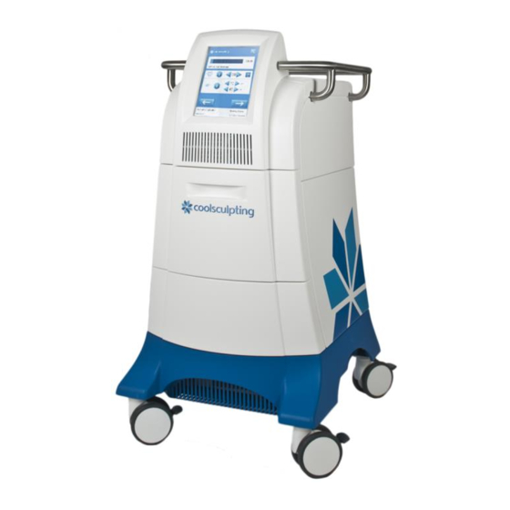
Page 23: System Overview
H A P T E R YSTEM VERVIEW Contents • Control Unit ..................23 • Applicators ..................33 • Supplies................... 35 This chapter describes the system. Control Unit The control unit is a portable device that is used to start, stop, and monitor treatments. •... - Page 24 Control Unit System Overview General Controls and Cues on the Screen The screen on the control unit displays cues and control buttons. Button Description Name Pay attention to safety concerns. Caution Connect the applicator to the control unit. Applicator? Cue Insert the card into the slot on the applicator.
- Page 25 System Overview Control Unit Controls and Cues for Standard Vacuum Applicators See also the directions for use for CoolAdvantage and CoolMini applicators. The screen on the control unit displays the following controls and cues when a standard vacuum applicator is connected to the control unit.
- Page 26 Control Unit System Overview Button Description Name Increase Increase Decrease Decrease Indicates that the system is preparing for the next Progress Indicator action. Table 8: Controls and Cues - Standard Vacuum Applicator Controls and Cues for CoolAdvantage Applicators See also the CoolAdvantage Directions for Use. The screen on the control unit displays the following controls and cues when a CoolAdvantage applicator is connected to the control unit.
- Page 27 System Overview Control Unit Button Description Name On - Press to turn off. Table 9: Controls and Cues - CoolAdvantage Applicators Controls and Cues for the CoolMini Applicator See also the CoolMini Directions for Use. The screen on the control unit displays the following controls and cues when a CoolMini applicator is connected to the control unit.
- Page 28 Control Unit System Overview Button Description Name Decrease Decrease Table 10: Controls and Cues - CoolMini Applicator Controls and Cues for the Surface Applicator The screen on the control unit displays the following cues and controls when a surface applicator is connected to the control unit.
- Page 29 System Overview Control Unit Body Profile Screen The Body Profile screen shows outlines of a male or female patient. In this example, a female patient is displayed. ► To select a treatment site: 1. Press the desired body part. If the selected part is not available, the system emits a tone. In this example, the flanks are selected for a female patient.
- Page 30 3. Latches: The latches lock the upper and lower modules of the control unit together. 4. Antenna: The antenna and data modem send data to ZELTIQ. (Availability and use of the data modem are subject to regional limitations.) 5.
- Page 31 System Overview Control Unit Power Cord Clamp The power cord clamp attaches the power cord to the rear of the control unit. Install the power cord clamp before using the system. If the power cord is dislodged during a treatment, the treatment will be ended abruptly.
- Page 32 1. Upper Port: The upper USB port (rectangular) is intended for use with approved software and hardware provided by ZELTIQ. 2. Lower Port: The lower USB port (square) is for use by ZELTIQ Customer Service personnel. Do not use the service port.
-
Page 33: Applicators
However, clinicians should consider all physical aspects of the area to be treated and use the applicator that will fit best for each patient. ZELTIQ defines a specific combination of treatment temperature and duration for each profile. Typically, a colder treatment temperature is paired with a shorter treatment duration. - Page 34 Applicators System Overview Applicator Total Treatment Sites Profile Profile Default Default Pre- Post- Cooling Area Temp. Duration Massage Vacuum treatment treatment Range Range Settings Setting Skin Care Care Option CoolFit Vertical bulges of Down to - Up to 60 (Optional) Skin wipes Manual pinchable fat,...
-
Page 35: Supplies
Insert a Card on page 40 • Select a Profile on page 41 Coolant The control unit requires an adequate supply of ZELTIQ coolant. When the coolant level is low, a Recoverable Exception message is displayed. Foam Borders Foam borders minimize movement of the surface applicator during treatment. Refer to the directions for use for foam borders. - Page 36 Supplies System Overview This page intentionally left blank. BRZ-101-TUM-EN2-L...
-
Page 37: Treatment
H A P T E R REATMENT Contents • Overview ..................37 • Perform a Treatment ..............37 • Perform Another Treatment ............45 • Cancel a Treatment ................ 47 • About Restarting a Treatment ............48 • Complete a Treatment ..............49 Overview A treatment is comprised of timed segments of cooling and heating;... - Page 38 Perform a Treatment Treatment Set up the Control Unit ► To set up the control unit: 1. Position the control unit next to the bed or chair to be used for the treatment. 2. Ensure that the vents on all four sides of the system have adequate ventilation. 3.
- Page 39 Treatment Perform a Treatment 4. With the locking lever in the Unlocked position, press the applicator connector down onto the connector plate gently but firmly. 5. When the connector meets resistance, stop pressing down. 6. Turn the locking handle 180° clockwise to the Locked position. The connector is pulled into the connector plate and locked in place.
- Page 40 Perform a Treatment Treatment Insert a Card ► To insert a card: 1. Align the card to the slot on the applicator. For CoolAdvantage and CoolMini applicators, insert the card into the slot on the applicator adapter. 2. Insert the card into the slot. The card is authenticated.
- Page 41 Treatment Perform a Treatment 3. On the Body Profile screen, select a treatment site. In this example, the flanks are selected for a female patient. Refer to the Preface for warnings and cleared intended use. 4. Press the Next button. 5.
- Page 42 Perform a Treatment Treatment Vacuum Applicator Treatment • For a CoolAdvantage treatment, see the CoolAdvantage Directions for Use. • For a CoolMini treatment, see the CoolMini Directions for Use. If a liner is detected, the button is displayed. GELPAD? If no liner is detected, the cue is displayed.
- Page 43 Treatment Perform a Treatment ► To apply a vacuum applicator: The use of this device on areas with superficially located nerve branches, arteries, or veins has not been demonstrated to be safe and effective. Such use may result in injury to the patient. If the gelpad slips and the cooling surfaces of the applicator come into direct contact with the patient’s skin, tissue injury may result.
- Page 44 Perform a Treatment Treatment 1. Remove jewelry that is in or directly adjacent to the treatment site. CAUTION: Prepare the treatment site with an alcohol wipe. 2. Apply one pair of foam borders around the treatment site. CAUTION: Refer to the directions for use for your foam borders. 3.
-
Page 45: Perform Another Treatment
Treatment Perform Another Treatment Perform Another Treatment ► To perform another treatment on the same patient: CAUTION: When the vacuum is turned off or the securement system straps are released, the applicator may disengage from the patient. The applicator could fall and be damaged or cause injury. - Page 46 Perform Another Treatment Treatment 3. Press the Next button. 4. Press the appropriate button for the current patient and treatment site. The Profile panel is displayed. • See Select a Profile on page 41. ► To perform a treatment on the next patient: CAUTION: When the vacuum is turned off or the securement system straps are released, the applicator may disengage from the patient.
-
Page 47: Cancel A Treatment
Treatment Cancel a Treatment Cancel a Treatment A treatment can be canceled by the system or by the operator. ► To cancel a treatment in the first 10 minutes: 1. Press the Interrupt button. 2. Press the Cancel button. 3. Press the button. -
Page 48: About Restarting A Treatment
About Restarting a Treatment Treatment About Restarting a Treatment A treatment can be interrupted by either the operator or the system. When you restart a treatment, the treatment count on the card is not reduced further. Each treatment can be restarted only once. A treatment can be restarted if: •... -
Page 49: Complete A Treatment
Treatment Complete a Treatment Restart a Treatment CAUTION: When the vacuum is turned off or the securement system straps are released, the applicator may disengage from the patient. The applicator could fall and be damaged or cause injury. Grasp the head of the applicator firmly before turning off the vacuum or releasing the securement system straps. - Page 50 Complete a Treatment Treatment Remove a vacuum applicator: Remove a surface applicator: Remove the gelpad or gel from the treatment site. Remove the liner, gelpad, and foam borders from the treatment site. Remove the liner from the applicator cup. Discard the used gelpad or gel, and liner according to your Discard the used liner, gelpad, foam borders, and site’s medical waste protocols.
- Page 51 Treatment Complete a Treatment 6. If necessary, adjust the position of the vacuum applicator and modify the vacuum pressure for massage. 7. If you turn off the vacuum and then remove the vacuum applicator from the site: a) Discard the used gelpad or gel according to your site’s medical waste protocols. b) Clean the treatment site.
- Page 52 Complete a Treatment Treatment This page intentionally left blank. BRZ-101-TUM-EN2-L...
-
Page 53: Cleaning And Maintenance
H A P T E R LEANING AND AINTENANCE Contents • Cleaning ..................53 • Maintenance ................... 54 • Disassembling the Control Unit ............57 • Assembling the Control Unit ............60 • Connecting Latches, Hoses, and Cables .......... 61 •... -
Page 54: Maintenance
Maintenance Cleaning and Maintenance ► To clean the touch screen: 1. Dampen a soft lint-free cloth with isopropyl alcohol or a window cleaning fluid. 2. Wipe the touch screen gently. Maintenance External Chiller Filter The CoolSculpting control unit has an external filter installed that is located on the front bottom of the system (Picture A) and is easily replaceable. - Page 55 Cleaning and Maintenance Preventive Maintenance ► How to replace the external chiller filter: Turn the control unit off prior to replacing the filter Preventive Maintenance As a rule, replace the chiller filter every six months. However, if the cooling cue (blue thermometer) is displayed indefinitely, or if the Z802-322 Chiller Pump Error message is displayed, replace the chiller filter promptly.
- Page 56 When the level of coolant is low, the control unit displays a message. It is safe to add coolant while the control unit is powered on. CAUTION: The use of unauthorized coolant has not been tested. Always use coolant authorized by ZELTIQ. ► To add coolant: 1. Locate the chiller tank cap.
-
Page 57: Disassembling The Control Unit
Cleaning and Maintenance Disassembling the Control Unit The amount of additional coolant that is required can vary. To avoid spillage, watch the coolant as you pour. Listen for changes in the sound. 6. Replace the cap and tighten it just until snug. When the vacuum is activated, it pulls the cap in tighter. - Page 58 Disassembling the Control Unit Cleaning and Maintenance 1. Flip the handle of the latch upward and turn it counterclockwise until the top of the clasp disengages. 2. Pull the handle back and let it hang downward. Cables and Hoses ► To disconnect cables and hoses: 1.
- Page 59 Cleaning and Maintenance Disassembling the Control Unit 2. Let the cover hang down, exposing the cables and hoses. 3. Working from left to right, disconnect the cables and then the hoses. ► To disconnect the data modem cable: If the data modem cable is disconnected, skip this step. 1.
-
Page 60: Assembling The Control Unit
Assembling the Control Unit Cleaning and Maintenance Remove Upper Module ► To remove the upper module: 1. Engage the locks on all four casters. 2. Prepare a place to put the upper module. 3. Position each person on one side of the control unit. 4. -
Page 61: Connecting Latches, Hoses, And Cables
Cleaning and Maintenance Connecting Latches, Hoses, and Cables 6. Ensure that the cables and hoses are clear. 7. Connect the latches, cables, and hoses. 8. Ensure that the upper module is aligned to the base module. Connecting Latches, Hoses, and Cables ►... -
Page 62: Customer Service
2. Ensure that the USB symbol is facing upward. 3. Insert the head of the cable into the upper USB port. Customer Service To report issues with the performance or use of your System, contact ZELTIQ Customer Service. • Worldwide: (+1) 925-474-8160 •... -
Page 63: Appendix A System Messages
P P E N D I X YSTEM ESSAGES Contents • ZELTIQ Customer Service ..............63 • Recoverable Exceptions ..............63 • Error Messages ................65 • General Messages................65 • Software Updates and Messages ........... 66 This appendix lists system messages with the suggested user action, if any. Each message includes a message code that is preceded by the letter Z and a Customer Service code. - Page 64 Manual. • Another medical device in close proximity If the problem persists, contact Customer Service. This system must be serviced by ZELTIQ no later than YYYY- Contact Customer Service. MM-DD to ensure continued use. Z428-YYY The applicator adapter and applicator are incompatible.
-
Page 65: Error Messages
System Messages Error Messages Error Messages For all system errors, power the control unit off and on. If the problem persists, call Customer Service. (ZELTIQ Customer Service on page 61) Code Message Z801 Chiller error. Z801-YYY Z802 Chiller error. Z802-YYY Z803 Control unit error. -
Page 66: Software Updates And Messages
Software Updates and Messages System Messages Software Updates and Messages From time to time, ZELTIQ may provide software updates. Button Description Name A software update is available. Software Update Install the software update. Install Clear the software update code. Clear Delete the last character of the patient number. - Page 67 System Messages Software Updates and Messages CoolAdvantage Software Updates and Messages In addition to the general software update messages, the following information may be displayed during a CoolAdvantage software update. Software Update: Attach the applicator adapter to the control unit. Approximate installation time: xx minutes Installation must be performed no later than YYYY/MM/DD to ensure continued use.
- Page 68 Software Updates and Messages System Messages This page intentionally left blank. BRZ-101-TUM-EN2-L...
-
Page 69: Appendix B System Tools
The date of the event as Month, DD, YYYY. Time The time of the event as HH:MM where H = hour and M = minute. Code The ZELTIQ error code. Condition A description of the condition: Recoverable, System Error, Treatment Error. Text The text of the control unit message. - Page 70 Availability and use of the data modem are subject to regional limitations. The Upload Data button is displayed only if the modem is activated. The data upload function is for use during a call with customer service. ► To upload data to ZELTIQ: 1. On the screen, press the Upload Data button.
-
Page 71: Card Log Screen
System Tools Card Log Screen Card Log Screen screen displays information about card usage. View the screen when you have questions Card Log Card Log about the number of cycles remaining and when treatments were performed. Heading Description Date The date of the usage: Month, DD, YYYY. Time The time of the usage as HH:MM, where H = hour and M = minute, in AM/PM. -
Page 72: Service Screen
Display the Chiller Diagnostic screen to view information about the Chiller Diagnostic performance of the chiller. The data modem can upload data to ZELTIQ. Availability and use of the Data Modem data modem are subject to regional limitations. Table 24: Controls for Service Tools ►... - Page 73 System Tools Service Screen screen is displayed. Vacuum Diagnostic Standard Vacuum Applicator Vacuum Applicator with Adapter On the sample screens, the applicator is disconnected and vacuum power is off. 2. Follow the instructions provided by Customer Service. 3. To return to the System Tools screen, press the Previous button. Chiller Diagnostic Screen c screen provides information about the performance of the chiller.
-
Page 74: Settings Screen
Settings Screen System Tools Data Modem Screen Availability and use of the data modem are subject to regional limitations. Contact customer service for further information. ► To view the Data Modem screen: 1. On the screen, press the button. Service Data Modem screen is displayed. - Page 75 System Tools Settings Screen screen is displayed. Settings 2. To return to the System Tools screen, press the Previous button. Calibration Screen The system screen might require recalibration from time to time. If the screen does not respond accurately to your touch, calibrate the screen.
- Page 76 Settings Screen System Tools 6. To discard your new settings and retain the previous settings, wait until the time runs out, approximately 30 seconds. screen is displayed. Settings Time Zone Screen The setting on the screen determines the time zone for entries on the screen and Time Zone Card Log...
- Page 77 System Tools Settings Screen 7. On the screen, press the button. Settings Date & Time Date and Time Screen Ensure that the Time Zone setting is correct before you modify Date and Time settings. ► To modify date and time settings: 1.
- Page 78 Settings Screen System Tools Data Screen screen displays the button. The button controls the display of patient Data Usage Metrics Usage Metrics data controls. The tools on the Data screen are for use during a call with Customer Service. ► To view the Data screen: 1.
-
Page 79: Essential Performance
P P E N D I X YSTEM PECIFICATIONS Contents • Essential Performance ..............79 • Disposal of Hazardous Materials ............ 79 • Environmental Requirements ............79 • Electrical Specifications ..............80 • Medical Safety Standards ............... 80 • Electromagnetic Compatibility ............80 •... -
Page 80: Electrical Specifications
Electrical Specifications System Specifications Dimensions of the Control Unit and Modules Height Depth Width Weight Control unit alone 47.5 in 35 in 24 in 215 lbs 120.7 cm 88.9 cm 61 cm 97.5 kg Control unit with support arm 62 in 216 lbs 157.5 cm 98.0 kg... - Page 81 See System Overview on page 23. CAUTION: Do not use cables or accessories other than those provided by ZELTIQ. The use of other cables or accessories may result in increased electromagnetic emissions or decreased immunity to such emissions.
- Page 82 Electromagnetic Compatibility System Specifications Guidance and Manufacturer’s Declaration -- Electromagnetic Immunity The system is intended for use in the electromagnetic environment specified below. The customer or user of the system should ensure that it is used in such an environment. Immunity Test IEC 60601 Compliance Level...
- Page 83 System Specifications Electromagnetic Compatibility Guidance and Manufacturer’s Declaration -- Electromagnetic Immunity The system is intended for use in the electromagnetic environment specified below. The customer or user of the system should ensure that it is used in such an environment. Immunity Test IEC 60601 Compliance...
-
Page 84: Data Modem Specifications
The data modem is a 4G LTE with HSPA+ fallback embedded cellular modem: Manufacturer: Multitech Model: MTSMC-LAT3 IC 5131A-LE910NAV2 FCC ID RI7LE910NAV2 Use the modem only with the antenna provided by ZELTIQ. Frequencies Network Type Effective Radiated Power 700MHz (B12/B13) / 850MHz (B5) 0.2W... - Page 85 United States of America The CoolSculpting System with the data modem has been tested and found to comply with the limits for a Class A digital device, pursuant to part 15 of the FCC Rules. These limits are designed to provide reasonable protection against harmful interference when the equipment is operated in a commercial environment.
- Page 86 ZELTIQ Aesthetics, Inc. 4410 Rosewood Drive Pleasanton, CA 94588 USA (925) 474-2500 www.coolsculpting.com 10/2018...
Need help?
Do you have a question about the CoolSculpting System and is the answer not in the manual?
Questions and answers