
Related Manuals for Badger Meter Flo-tech PFM Series

Summary of Contents for Badger Meter Flo-tech PFM Series
- Page 1 PFM Portable Hydraulic Testers PFM6, PFM6BD, and PFM8 Badger Meter ® Installation & Operation Manual 05-TUR-UM-00193-EN (September 2012)
- Page 2 PFM Portable Hydraulic Testers PFM6, PFM6BD, and PFM8 Page ii September 2012...
-
Page 3: Table Of Contents
CONTENTS INTRODUCTION PFM6 Digital Hydraulic Tester PFM6BD Bi-directional Hydraulic Tester PFM8 Digital Hydraulic Tester & Dynamometer SPECIFICATIONS CALIBRATION SERIES/MODEL NUMBER DESIGNATIONS DIMENSIONS INSTALLATION OPERATION TEST PROCEDURES General Information Standard Test Conditions Pump Test “Tee” Test Control Valve, Cylinder and Hydraulic Motor Test Relief Valve in Separate Housing Relief Valves MAINTENANCE / TROUBLESHOOTING... - Page 4 FIGURES HYDRAULIC TESTER DIMENSION ILLUSTRATION PFM6 AND PFM6BD TOGGLE SWITCH PFM8 SLIDE AND MEMBRANE SWITCHES PUMP TEST “TEE” TEST CONTROL VALVE, CYLINDER AND HYDRAULIC MOTOR TEST (PFM6BD) PFM6 AND PFM8 BURST DISC PFM6BD BURST DISCS BATTERY REPLACEMENT TABLES SPECIFICATIONS MODEL NUMBER DESIGNATIONS DIMENSIONS VISCOSITY CONVERSION...
-
Page 5: Introduction
PFM Portable Hydraulic Testers PFM6, PFM6BD, and PFM8 INTRODUCTION Flo-tech Portable Hydraulic Testers are designed to provide fast diagnostic troubleshooting of hydraulic systems and components These compact, self-contained testers feature laboratory accuracy and provide flow, temperature, pressure and optional power measurements simultaneously from one point Flo-tech offers three models, all available in a choice of up to 5 flow ranges and 3 port sizes: PFM6 Digital Hydraulic Tester Features:... -
Page 6: Specifications
PFM Portable Hydraulic Testers PFM6, PFM6BD, and PFM8 SPECIFICATIONS MATERIAL Housing: 6013-T351 Anodized aluminum Turbine Rotor: T416 Stainless steel Rotor Supports: 6061-T6 Aluminum Buna N standard Seals: Viton® and EPR optional Ball Bearings: 440 C Stainless steel Hub Cones: 6061-T6 Aluminum alloy Temperature Probe: 12L14 Steel, electroless nickel plate PFM6/8 SERIES TESTERS... -
Page 7: Calibration
PFM Portable Hydraulic Testers PFM6, PFM6BD, and PFM8 CALIBRATION Testers are calibrated with a 32 cSt (150 SUS) hydraulic oil Standard calibration is done using 5 points and is traceable to NIST, ISO 9001 An optional 10 point calibration can be performed for increased accuracy SERIES/MODEL NUMBER DESIGNATIONS NOMINAL PORT SERIES... -
Page 8: Dimensions
PFM Portable Hydraulic Testers PFM6, PFM6BD, and PFM8 DIMENSIONS Figure 1: Hydraulic Tester Dimension Illustration - PFM6 and PFM8 Series - PFM6BD Series DIMENSIONS LENGTH (A) × DEPTH (B) × HEIGHT (C) SERIES WEIGHT LBS (KG) INCHES PFM6-15 11 3 × 3 5 × 9 8 287 ×... -
Page 9: Installation
PFM Portable Hydraulic Testers PFM6, PFM6BD, and PFM8 CAUTION Caution - Read instructions thoroughly before installing the tester. If you have any questions regarding product installation or maintenance, call your local supplier or the factory for more information. INSTALLATION CAUTION Caution - The information in this manual is for general application only. -
Page 10: Pfm6 And Pfm6Bd Toggle Switch
PFM Portable Hydraulic Testers PFM6, PFM6BD, and PFM8 Toggle Switch Figure 2: PFM6 and PFM6BD Toggle Switch Flow is identified by the symbol and the symbol indicates temperature Horsepower readings will be followed by the symbol and kilowatt by a symbol NOTE: If no flow has been present for five minutes, the power saver circuit will automatically shut the PFM8 off Pressing the “ON”... -
Page 11: Pfm8 Slide And Membrane Switches
PFM Portable Hydraulic Testers PFM6, PFM6BD, and PFM8 The PFM6 and PFM8 testers are equipped with a poppet style loading valve The PFM6BD testers utilize a spool design loading valve to accommodate bi-directional flow The spool design requires more turns to go from total open to total close Flo-check U.S. -
Page 12: Test Procedures
PFM Portable Hydraulic Testers PFM6, PFM6BD, and PFM8 TEST PROCEDURES WARNING Warning - All testers are shipped with the loading valve in the closed position. The loading valve must be opened fully before initiating flow and testing of the hydraulic circuit. Turn the loading valve handle counterclockwise to the fully open position. -
Page 13: Pump Test
PFM Portable Hydraulic Testers PFM6, PFM6BD, and PFM8 Pump Test A tee must be installed between the pump discharge port and the return line to the tank Be sure the fluid path is only through the pump, the hydraulic test unit, and back to the tank DO NOT STAND IN FRONT OF PRESSURE RELIEF DISK VENT. -
Page 14: Tee" Test
PFM Portable Hydraulic Testers PFM6, PFM6BD, and PFM8 “Tee” Test A tee must be installed between the pump and control valve and connected to the “IN” port of the PFM tester The “OUT” port of the tester is connected to the tank Pumps and relief valves can be isolated from the system and checked with the “Tee” Test CONTROL VALVE... - Page 15 PFM Portable Hydraulic Testers PFM6, PFM6BD, and PFM8 WARNING Warning - Increase pressure slowly. The relief valve may now be isolated from the hydraulic circuit, and system pres- sures higher than the relief valve setting can result in injury to personnel and/or damage to the equipment. Pump Test Plug the line to the control valve Open the tester loading valve fully to read maximum pump flow at zero pressure...
-
Page 16: Control Valve, Cylinder And Hydraulic Motor Test
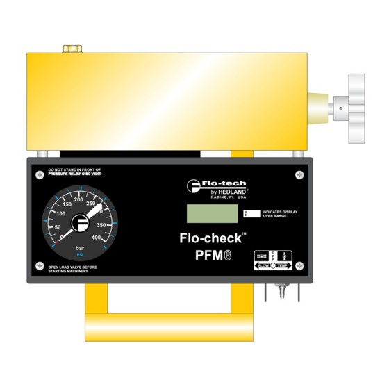
PFM Portable Hydraulic Testers PFM6, PFM6BD, and PFM8 Control Valve, Cylinder and Hydraulic Motor Test IN / OUT HYDRAULIC MOTOR CONTROL VALVE DO NOT STAND IN FRONT OF PRESSURE RELIEF DISK VENT. by HEDLAND RACINE, WI. USA INDICATES DISPLAY OVER RANGE. Flo-check PFM BD FLOW... -
Page 17: Relief Valve In Separate Housing
PFM Portable Hydraulic Testers PFM6, PFM6BD, and PFM8 Put one control valve in an operating position (Only one control valve should be in an operating position at any one time ) Slowly close the tester loading valve to achieve the pressure obtained in Step 3 under Pump Test or Step 1 c under “Tee” Test and record the flow Repeat for all operating positions of all control valves If all components are in good operating condition, pressure and flow measurements should be the same as in Step 3 of the Pump Test... -
Page 18: Maintenance / Troubleshooting
PFM Portable Hydraulic Testers PFM6, PFM6BD, and PFM8 MAINTENANCE / TROUBLESHOOTING The PFM testers are designed to give years of trouble-free service However, if trouble is suspected, a few simple checks can be made Load Valve If the valve fails to load the system, remove the valve body and check for foreign material, worn parts or seals Flow The absence of any flow reading may indicate a blockage of the turbine Remove the retaining ring from the inlet port and carefully remove the turbine assembly Remove any material that may be preventing easy rotation of the rotor... -
Page 19: Pfm6 And Pfm8 Burst Disc
PFM Portable Hydraulic Testers PFM6, PFM6BD, and PFM8 Burst Disc Procedure for PFM6 and PFM8 Testers Position the tester block to expose the internal burst disc body as shown in Figure 7 Loosen the burst disc body from the flow meter block Remove the burst disc body from the flow meter block Remove the ruptured burst disc from the flow meter block and discard Clean out the burst disc port Remove any debris from the sealing surfaces... -
Page 20: Pfm6Bd Burst Discs
PFM Portable Hydraulic Testers PFM6, PFM6BD, and PFM8 Burst Disc Procedure for PFM6BD Position the PFM6BD to expose the internal burst disc body as shown in Figure 8 Loosen the burst disc body from the flow meter block Remove the burst disc body from the flow meter block Remove the ruptured burst discs from the flow meter block and discard Retain the support ring Clean out the burst disc port and the support ring Remove any debris from the sealing surfaces Rotate the tester to face the burst disc port upwards and drop in a new burst disc Make sure it lies flat on the sealing surface en-... -
Page 21: Battery Replacement
PFM Portable Hydraulic Testers PFM6, PFM6BD, and PFM8 Battery Replacement All PFM testers utilize four AA size alkaline batteries These batteries will normally provide approximately 50 hours of service before a low battery condition is indicated On the PFM6 and PFM6BD, a LO BAT signal on the display indicates a low battery condition On the PFM8, a flashing colon (:) on the display indicates a low battery condition When a low battery condition has been displayed, immediately remove discharged batteries from the tester to prevent battery holder corrosion To change the batteries, remove the 4 screws on the cover assembly Pull the cover slowly upward to clear the internal... -
Page 22: Flow Vs Pressure Drop Charts Δp Captured Using Loading Valves
PFM Portable Hydraulic Testers PFM6, PFM6BD, and PFM8 FLOW VS PRESSURE DROP CHARTS ΔP CAPTURED USING LOADING VALVES PFM6-15, PFM8-15 PFM6-30, PFM8-30 FLOW, GPM FLOW, GPM PFM6-60, PFM8-60 PFM6-85, PFM8-85 90 100 FLOW, GPM FLOW, GPM PFM6-200, PFM8-200 PFM6BD-60 Forward Reverse FLOW, GPM FLOW, GPM... -
Page 23: Hydraulic Formulas And Viscosity Information
PFM Portable Hydraulic Testers PFM6, PFM6BD, and PFM8 HYDRAULIC FORMULAS AND VISCOSITY INFORMATION Flow Rate Formulas × K GPM Frequency (Hz) = GPM = × K-Factor (K) = Time Base (TB) = Flow Rate Related Formulas × Flow Rate (GPM) Fluid Speci c Gravity Valve C Factor = ∆... -
Page 24: Fluid Viscosity Conversion Table
PFM Portable Hydraulic Testers PFM6, PFM6BD, and PFM8 FLUID VISCOSITY CONVERSION TABLE SAYBOLT UNIVERSAL ISO-VG CENTISTOKE CENTIPOISE¹ TYPICAL BRANDS/LIQUIDS AT 100 °F SECONDS (SUS) 0 876 Water 2 19 3 68 5 17 6 57 Kerosene 7/10 7 71 Atlantic Richfield/Duro 55 Hydraulic Oil 10 5 9 20 Monsanto/Skydrol - 500 A... -
Page 25: Return Goods Authorization
PFM Portable Hydraulic Testers PFM6, PFM6BD, and PFM8 RETURN GOODS AUTHORIZATION When returning equipment for service, a Returned Goods Authorization (RGA) number must be obtained from our Service Department Please contact them by phone at 800-433-5263 or 262-639-6770 or by e-mail to info@flo-tech com All returns go to the following address and must include the RGA number on the outside of the box: Flo-tech... - Page 26 PFM Portable Hydraulic Testers PFM6, PFM6BD, and PFM8 INTENTIONAL BLANK PAGE Materials and specifications subject to change without notice Page 26 September 2012...
- Page 27 With respect to products not manufactured by Badger Meter, the warranty obligations of Badger Meter shall in all respects conform The Badger Meter warranty shall apply to the Flo-tech and be limited to the warranty extended to Badger Meter by the Portable Hydraulic Testers (“Product”). supplier.
- Page 28 The Americas | Badger Meter | 4545 West Brown Deer Rd | PO Box 245036 | Milwaukee, WI 53224-9536 | 800-876-3837 | 414-355-0400 México | Badger Meter de las Americas, S.A. de C.V. | Pedro Luis Ogazón N°32 | Esq. Angelina N°24 | Colonia Guadalupe Inn | CP 01050 | México, DF | México | +52-55-5662-0882 Europe, Middle East and Africa | Badger Meter Europa GmbH | Nurtinger Str 76 | 72639 Neuffen | Germany | +49-7025-9208-0 Czech Republic | Badger Meter Czech Republic s.r.o.
Need help?
Do you have a question about the Flo-tech PFM Series and is the answer not in the manual?
Questions and answers