Table of Contents
Advertisement
Quick Links
Advertisement
Table of Contents

Related Manuals for Tenda M3

Summary of Contents for Tenda M3
- Page 1 Access Controller M3 User Manual...
- Page 2 Tenda reserves the right to make changes to the products without obligation to notify any person or organization of such revisions or changes. Tenda does not assume any liability that may occur due to the use or application of the product described herein. Every effort has been made in the preparation of this document to ensure accuracy of the contents, but all statements, information and recommendations in this document do not constitute the warranty of any kind, express or implied.
- Page 3 Preface Thank you for choosing Tenda! Please read this user guide before you start with M3. Conventions If not specifically indicated, “AC”, “this device” or “this product” mentioned in this User Guide stands for this AC. In this User Guide, we assume that all settings on this device are kept in default factory settings.
- Page 4 Virtual Local Area Network Technical Support If you need more help, contact us by any of the following means. We will be glad to assist you as soon as possible. Canada: 1-888-998-8966 support@tenda.cn Hong Kong: 00852-81931998 Hotline Email http://www.tendacn.com tendasz...
-
Page 5: Table Of Contents
Contents Know Your Device .............................. 1 1.1 Overview ..............................1 1.2 Apperance ..............................1 1.2.1 Front Panel ............................1 1.2.2 Rear Panel ............................2 1.2.3 Label ..............................2 1.3 Application Topology ........................... 3 Web Login ................................4 2.1 Web Login ..............................4 2.2 Web Logout .............................. - Page 6 3.2.3 VLAN policy ............................. 18 3.2.4 Maintain Policy ..........................20 3.3 Manage AP ..............................27 3.3.1 AP Group Modify ..........................27 3.3.2 AP Modify ............................32 3.4 User Status ..............................39 3.5 System Tools .............................. 40 3.5.1 System Status ..........................40 3.5.2 Network Setting ..........................
-
Page 7: Know Your Device
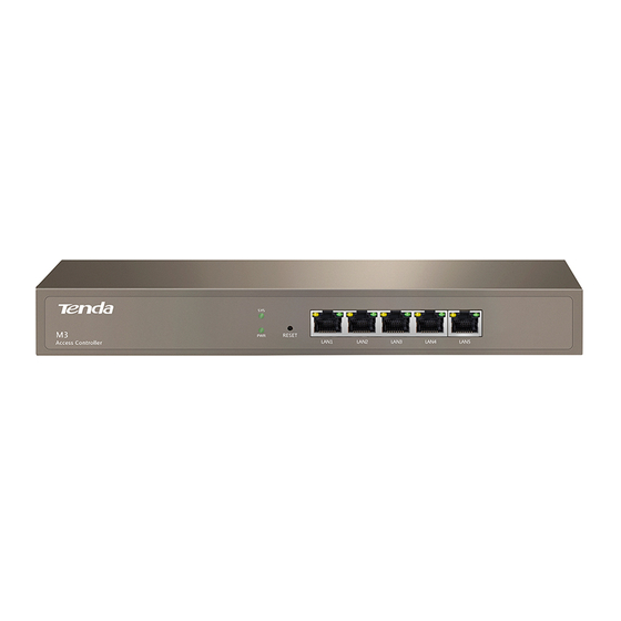
Know Your Device Overview Tenda M3 is a multifunctional access controller. It supports a maximum of 64 Tenda APs to be managed in a centralized manner, providing managemable and high-stable wireless network solutions to small-to-medium-sized enterprises, higher education institutions and hotels. -
Page 8: Rear Panel
LAN port Five 10/100/1000 Mbps auto-negotiation RJ45 ports. Each RJ45 port has its corresponding Link/Act LED. RESET button When the AC is functioning properly, press it with a needle for about 6 seconds and then release; about 45 seconds later, this device will be restored to factory settings. -
Page 9: Application Topology
Application Topology See the following figure below. Router Core Switch PoE Swicth Smartphone Tablet Laptop For simple networks with few APs, you can connect the PoE switch directly to M3. -
Page 10: Web Login
Web Login Web Login The first time you use this AC, you can access its web UI with the following default login information: Login information Default settings User Name admin Password admin IP Address 192.168.10.1 Step 1 Connect your PC to a LAN port of the AC directly, or to the switch connected to the AC. Step 2 Set your PC to an IP address within the following range: 192.168.10.X (2-254), which is 192.168.10.26 in this example, and with the subnet mask of 255.255.255.0. - Page 11 Step 3 Launch a web browser, input 192.168.10.1 in the address bar and press Enter. Step 4 Type in the default user name and password (admin/admin) and then click Login. Step 5 Then you can go to this device’s web UI to view corresponding configuration information or configure relevant settings.
-
Page 12: Web Logout
----End Web Logout You can safely exit this AC’s web UI by directly closing your web browser or clicking Logout in the upper right corner of the web UI. Layout of Web UI The Web page can be divided into three parts: navigation bar and the configuration section. ❷... -
Page 13: Commonly Used Elements On Ui
If features or parameters on the web UI display grey, they are not configurable. Commonly Used Elements on UI Port Graphical Status Overview: Commonly Used Elements Description Indicates no link is established over the corresponding port. Indicates a link has been established over the corresponding port. Commonly Used Buttons: Commonly Used Elements Description... -
Page 14: Function Descriptions
Function Descriptions Discover AP This section gives you an overview of the information of connected APs, including online and offline APs. Button Description: Button Description Used to scan the Aps in the network. Used to scan the enabled SSID information of online APs. Used to scan and saving results of Discover AP displayed on the page to your local computer as an excel spreadsheet. -
Page 15: Discover Ap
3.1.1 Discover AP Click Discover AP to enter the page below: Parameter Description: Parameter Description Model The model number of the AP. Remark The comment of the AP. By default, it indicates the model number of the AP. When the AP is online, click it to modify. -
Page 16: Discover Ssid
3.1.2 Discover SSID To scan SSIDs on your network, click Discover SSID, the scanned information will be displayed on the page. Parameter Description: Parameter Description Model The model number of the AP. Remark The comment information of the AP. By default, it indicates the model number of the AP. When the AP is online, click it to modify. -
Page 17: Export The Scanned Ssid Information
3.1.3 Export the scanned SSID information To export the scanned SSID information, click Export, the following window pops up, clikc OK, an Excel file is downloaded to your local computer. 3.1.4 Deleting offline APs Select the offline AP you wan to delete, click Delete. -
Page 18: Manage Policy
Manage Policy This section helps you create SSID Policy, Radio Policy, VLAN Policy, and Maintain Policy. 3.2.1 SSID Policy Here you can view the basic information of SSID policies. SSID parameters include SSID, Security key, VLAN ID, and so on. To create an SSID policy, click Manage Policy >... - Page 19 Button Description You are not recommended to modify the Used policies. Add SSID Policy To create an SSID policy, click + Add . Parameter Description: Parameter Description Policy Enter a unique policy name. SSID Enter the SSID to which the policy applies. The length of the SSID ranges from 1 to 32 bytes. The AC supports the following three types of Security Mode: Security ...
- Page 20 Parameter Description WPA-PSK: The security mode of the wireless network is WPA-PSK. WPA2-PSK: The security mode of the wireless network is WPA2-PSK. WPA-Enterprise: The security mode of the wireless network is WPA-Enterprise. WPA2-Enterprise: The security mode of the wireless network is WPA2-Enterprise. It is available only when Security is enabled.
-
Page 21: Radio Policy
3.2.2 Radio Policy Here you can view the basic information of Radio policies including 5G Prority, Radio, Mode, Bandwidth, Channel, Time Age, and so on. To create a radio policy, click Manage Policy > Radio Policy to enter the page below. Button Description: Button Description... - Page 22 Parameter Description: Parameter Description Policy Enter a unique policy name. Supports 2.4 GHz and 5 GHz bands. Different radio provides different signal strength and quality over Radio different distance ranges. 2.4 GHz offers long distance data transmission, while the 5 GHz offers high-speed data transmission.
- Page 23 Parameter Description Select a Network Mode. 2.4 GHz band includes 11b, 11g, 11b/g and 11b/g/n, while 5 GHz band includes 11a, 11ac and 11a/n. Descriptions are as follows. 11b: Works in 2.4 GHz band and supports up to 11 Mbps. ...
-
Page 24: Vlan Policy
Parameter Description connect to 5 GHz band in higher prority, which helps the AP to reduce interference and workload in 2.4 GHz band and hence improve user experience. Status Display whether the Policy is used or not. Use for modifying the parameters except Policy name. Action You are not recommended to modify the Used policies. - Page 25 Parameter Description: Parameter Description Policy Enter a unique VLAN Policy name. Enable/disable AP's 802.1Q VLAN feature. AP VLAN After this feature is enabled and this VLAN policy is delivered to AP, "VLAN ID" in Manage Policy > SSID policy takes effect. PVID Enter the VLAN ID of AP’s Trunk port.
-
Page 26: Maintain Policy
Parameter Description You are not recommended to modify the Used policies. 3.2.4 Maintain Policy Here you can view the information of maintain policies. To create a maintain policy, alert policy, admin policy or deployment policy, click Manage Policy > Maintain Policy to enter the page below. - Page 27 Parameter Description Signal interference between APs can be effectively reduced by adjusting the transmit power of AP. If it Signal Transmission is a capacity-oriented network, please select High Density. Otherwise, select Coverage. Select a Signal Reception Method based on different scenarios. ...
- Page 28 Parameter Description: Parameter Description Policy Enter a unique policy name. Duplicated names are not allowed. Use to turn on or off the AP’s LED indicators. Enable/Disable AP’s auto reboot feature. If enabled, the AP will automatically reboot at a specified time Auto Maintain (recommended in leisure time) to ensure AP’s performance.
- Page 29 Parameter Description: Parameter Description Policy Enter a unique policy name. Duplicated names are not allowed. Enable/Disable the software alert function. When enabled, please enter the IP address of the host used to receive alert logs, and the AC will send alert logs directly to the alert client program running on the host.
- Page 30 Parameter Description Traffic Limit When AP Traffic Alert is enabled, the AC will send alert logs when AP traffic reaches this limit. Enable/Disable AP Client Alert. The AC will send alert logs when the number of connected clients AP Client Alert reaches its limit.
- Page 31 ---End Admin Policy This section helps you configure login account and password of AP. Click + Admin Policy to add an admin policy. Parameter Description: Parameter Description Policy Enter a unique policy name. Duplicated names are not allowed. User name Set up AP's login account.
- Page 32 Deployment Policy This section helps you configure deployment policies, including Signal Transmission, Signal Reception, and Ethernet Mode. Click + Deployment Policy to add a deployment policy. Parameter Description: Parameter Description Policy Enter a unique SSID deployment policy name. Duplicated names are not allowed. Signal interference between APs can be effectively reduced by adjusting the transmit power of AP.
-
Page 33: Manage Ap
Manage AP This section helps you deliver the configured policies to appropriate APs and manage the APs. It includes two parts, AP Group Modify and AP Modify. 3.3.1 AP Group Modify Here you can view the basic information and policy of the connected APs. To deliver SSID policy, radio policy, VLAN policy and maintain policy to APs, click Manage AP >... - Page 34 Parameter Description AP’s SSID(s). If more than one SSID is delivered to AP, it displays all SSIDs when the cursor is hovering SSID over. Radio Policy The delivered radio policy name. VLAN policy The delivered VLAN policy name. Maintain Policy The delivered maintain policy name.
- Page 35 SSID Setting To deliver SSID policies to online APs: Step 1 Log in to the web UI of AC, click Manage AP > AP Group Modify. Step 2 Select online APs. Step 3 Click SSID Setting. Step 4 From the drop-down list, select the SSID policy name. Step 5 Click Save.
- Page 36 Step 2 Select online APs. Step 3 Click RF Setting. Step 4 From the drop-down list, select the policy name. Step 5 Click Save. ----End The RF policy will be delivered to the selected online APs. VLAN Settings To deliver a VLAN policy to online APs: Step 1 Log in to the web UI of AC, click Manage AP >...
- Page 37 Step 1 Log in to the web UI of AC, click Manage AP > AP Group Modify. Step 2 Select online APs. Step 3 Click Maintain Policy. Step 4 From the drop-down list, select the corresponding policy name. Step 5 Click Save.
-
Page 38: Ap Modify
Step 2 Select the offline APs to be deleted. Step 3 Click Delete. ----End Online APs will not be deleted even if you select them. 3.3.2 AP Modify To reboot, upgrade and reset selected online APs, to delete selected offline APs or to change RF settings of an AP, click Manage AP >... - Page 39 Parameter Description Radio AP's frequency band. It may be 2.4 GHz or 5 GHz or 2.4 GHz and 5 GHz. AP’s SSID(s). If more than one SSID is delivered to AP, it displays all SSIDs when the cursor is hovering SSID over.
- Page 40 Reboot To reboot online APs: Step 1 Log in to the web UI of AC, click Manage AP > AP Modify. Step 2 Select online APs to be rebooted. Step 3 Click Reboot. ----End Upgrade To upgrade for online APs: Step 1 Log in to the web UI of AC, click Manage AP >...
- Page 41 ----End When an AP firmware is upgrading, please DO NOT power off the AP, otherwise it may cause damage to the AP! If a sudden power failure occurs, please upgrade again. If you cannot log in to AP's Web UI after a sudden power failure, please contact our technical support.
- Page 42 Modify Click on the right page to modify the AP's RF settings. Parameter Description: Parameter Description WiFi Enable/disable AP's WiFi in each band. Countries apply for their own regulations to the allowable channels, allowed users and maximum power levels within the frequency ranges. Consult your local authorities as these regulations may be out of date Country as they are subject to change at any time.
- Page 43 4: Automatically enable radio interference immunity and noise reduction. Different AP models have different recommended interference mode. Please contact Tenda technical support for help. AP’s wireless transmission power. If this value is greater than the maximum supported power of an AP, TX power the maximum supported power takes effect after the policy is delivered.
- Page 44 Parameter Description enter standby or sleep mode, it conserves energy. It is only effective when you enable WMM. After a client connects to the AP: Time Age For Client If there is no data transmission within the time period, AP will actively disconnect the client. If data transmission is detected within the time period, AP will recalculate the time age.
-
Page 45: User Status
User Status This section gives you an overview of client information connected to the network. Click User Status to enter the page below. To export and save the client information to your local computer, click Export, and then click OK on the pop-up window. -
Page 46: System Tools
Parameter Description Offline: The user does not authorize to the AP currently. System Tools This section helps you manage this AC in a safe and effective manner, and get to know the real-time running status. Here are the following 7 parts: ... - Page 47 Interface It displays the current connection status of each LAN port of the AC. System Status It displays how many APs are managed by the AC, offline AP numbers, connected client numbers, run time and CPU/memory usage of the AC.
-
Page 48: Network Setting
Parameter Description: Parameter Description Managed APs It indicates how many APs are managed by the AC currently. Offline APs It indicates how many APs are offline currently. Connected Clients It indicates how many wireless clients are connected to online APs currently. Run Time It indicates the time elapsed since the AC is rebooted last time. - Page 49 Network Setting to enter the page below. LAN Settings It allows you to set IP address, subnet mask, gateway, preferred DNS and alternate DNS.
- Page 50 Parameter Description: Parameter Description It specifies the IP address of this AC. Users in LAN can access the web UI of this AP using this IP address. The default IP is 192.168.10.1. IP Address If you change LAN IP, you still need to change the IP address on your computer to be the same segment of the new IP address.
- Page 51 Parameter Description: Parameter Description Start IP Enter the start IP address of DHCP address pool. Enter the end IP address of DHCP address pool. End IP Start IP and end IP must be on the same IP segment. Lease time is the assigned IP address’s effective time period. When lease time is due, the online APs can Lease Time renewal the lease time.
- Page 52 Step 2 Port Isolation: Set Port Isolation to Enable. Step 3 VLAN ID: Set VLAN ID, such as 3-10, or 12. One port can only be set with one VLAN ID, but can be grouped into different VLANs. The hyphen (-) means “consective”, and the comma (,) means “and”. For example, 3-10, 12 includes 9 VLAN IDs through VLAN3 to VLAN10, as well as VLAN12.
- Page 53 An example of configuring VLAN settings Network Topology Router F1226 PoE Switch Port7 Port8 Port1:VLAN2,3,4 Port5 Port3:VLAN3 Port2:VLAN2 Port4:VLAN4 Smartphone Laptop Tablet Topology description: (here takes F1226P as an example) Create 3 802.1Q VLAN rules on the switch, VLAN IDs and corresponding ports are as below: VLAN2: Interface 2, port link type is Access;...
-
Page 54: Dhcp List For Ap
Step 2 Port Isolation: Set Port Isolation to Enable. Step 3 VLAN ID: Set VLAN ID to 1-4. Step 4 LAN port: Set LAN port to LAN1. Step 5 Click Add. ----End Then click System Tools > Maintain to reboot this device to activate your settings. 3.5.3 DHCP List For AP Here you can view AP’s IP address obtained from AP’s DHCP server, and AP’s MAC address. -
Page 55: Maintain
3.5.4 Maintain Here you can view license information, modify user management information and maintain the AC. Click System Tools > Maintain to enter the page below. - Page 56 License The AC is licensed by default, and can manage up to 128 APs. User Management In order to prevent other person from modifying settings on your AC, it is advisable to modify your login user name and password. After modifying your login user name and password, it will automatically skip to the login page and you need to use the new user name and password to re-access its web UI.
- Page 57 Firmware Upgrade Firmware upgrage operation allows you to enjoy more functions and more stable performance. We recommend you go to www.tendacn.com to find out the corresponding software to upgrade the AC. When an AP firmware is upgrading, please DO NOT power off the AP, otherwise it may cause damage to the AP! If a sudden power failure occurs, please upgrade again.
-
Page 58: Date&Time
Method 1: Log in to the web UI of the AC, click System Tools > Maintain > Maintenance, and then click Reboot. Method 2: Disconnect the AC from power supply and then reconnect the AC to power supply. Backup Configuration If you have configured many settings on this device, which will make this device work in good status and suitable environment, it is suggested to backup settings for this device, which will be convenient for troubleshooting and saving time for next time configuration. - Page 59 Time configuration will be lost if the AC is powered off. But if you enable “NTP Network Time”, the AC will synchronize time with Internet after reboot. And then time-related functions will perform correctly. Parameter Description: Item Description System time The AC's current time.
- Page 60 Step 4 Sync Interval: Select a Sync Interval. It is recommended to keep the default value 30 minutes. Step 5 Click OK. ----End Synchronize with PC time When you click Synchronize with PC time, the AC will synchronize time with your computer. And you must ensure that your PC’s time is correct.
-
Page 61: System Log
3.5.6 System Log The log system can record and classify information such as AP connections and alarms, and help network administrators to monitor network operation and diagnose network faults. The most recent logs are displayed at first. A maximum of 3000 logs are allowed. If exceeded, old logs will be replaced with new ones. - Page 62 This AC provides Ping and Traceroute diagnosis tools. Ping Ping is a commonly used diagnosis and troubleshooting command. It consists of ICMP request and response packets. If the network works normally, the target device will return response packets. Parameter Description: Parameter Description Destination...
- Page 63 Parameter Description Packet Number The number of request packets. Packet Size The size of request packets. Traceroute Traceroute is computer network diagnostic tool for displaying the route (path) and measuring transit delays of packets across an Internet Protocol (IP) network.
-
Page 64: Appendix
Appendix Troubleshooting Q: I enter the device’s LAN IP address in the web browser but cannot access this device’s web UI. What should I do? Check the TCP/IP settings on your PC and verify that IP address is 192.168.10.X (2-254); −... -
Page 65: Default Factory Settings
Default Factory Settings Parameter Default Setting Login Method HTTP (web UI) Login IP 192.168.10.1 Login Information Login User name/Password admin/admin Web Logout 5 minutes Policy Configuration IP Address 192.168.10.1 Subnet Mask 255.255.255.0 LAN Settings Gateway 192.168.10.254 Preferred DNS 192.168.10.254 Alternative DNS Status Enabled Start IP...
Need help?
Do you have a question about the M3 and is the answer not in the manual?
Questions and answers