LG SH7B Service Manual

LG SH7B Service Manual

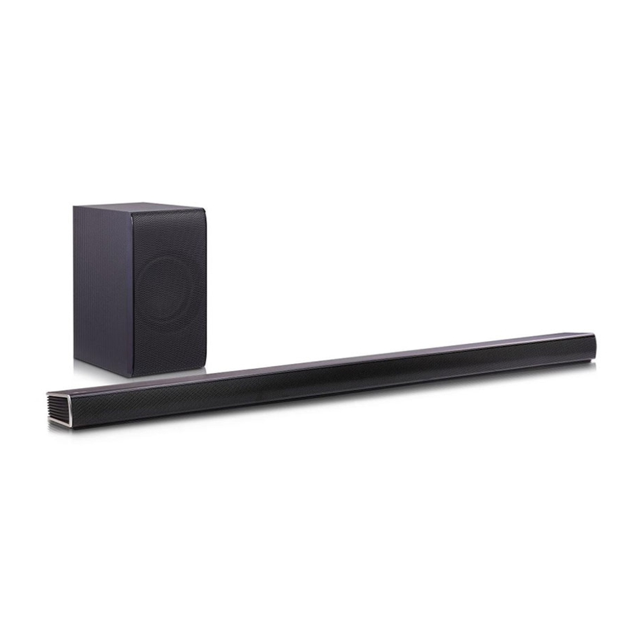
Smart hi-fi audio wireless multi-room sound bar
Hide thumbs Also See for SH7B:
Table of Contents

Advertisement

Internal Use Only
SMART Hi-Fi AUDIO
Wireless Multi-room Sound Bar
SERVICE MANUAL
MODEL: SH7B
(SH7B, SPH7B-W)
CAUTION
BEFORE SERVICING THE UNIT, READ THE "SAFETY PRECAUTIONS"
IN THIS MANUAL.
P/NO : AFN77195045
JANUARY, 2016

Advertisement

Table of Contents
loading

Summary of Contents for LG SH7B

  • Page 1 Internal Use Only SMART Hi-Fi AUDIO Wireless Multi-room Sound Bar SERVICE MANUAL MODEL: SH7B (SH7B, SPH7B-W) CAUTION BEFORE SERVICING THE UNIT, READ THE “SAFETY PRECAUTIONS” IN THIS MANUAL. P/NO : AFN77195045 JANUARY, 2016...
  • Page 2 CONTENTS SECTION 1 ..SUMMARY SECTION 2 ..CABINET & MAIN CHASSIS SECTION 3 ..ELECTRICAL SECTION 4 ..WIRELESS SUBWOOFER PART SECTION 5 ..REPLACEMENT PARTS LIST...
  • Page 3: Table Of Contents

    SECTION 1 SUMMARY CONTENTS PRODUCT SAFETY SERVICING GUIDELINES FOR AUDIO PRODUCTS ..........1-3 SERVICING PRECAUTIONS .......................... 1-4 • GENERAL SERVICING PRECAUTIONS • INSULATION CHECKING PRODEDURE • ELECTROSTATICALLY SENSITIVE (ES) DEVICES WIRELESS SUBWOOFER CONNECTION ....................1-5 HIDDEN MODE ..............................1-6 LAN UPDATE GUIDE ............................1-7 SOFTWARE UPDATE GUIDE ........................
  • Page 4: Product Safety Servicing Guidelines For Audio Products

    When servicing this product, under no circumstances should the original design be modified or altered without permission from LG Corporation. All components should be replaced only with types identical to those in the original circuit and their physical location, wiring and lead dress must conform to original layout upon completion of repairs.
  • Page 5: Servicing Precautions

    SERVICING PRECAUTIONS CAUTION: Before servicing the Audio products covered by this Electrostatically Sensitive (ES) Devices service data and its supplements and addends, read and fol- Some semiconductor (solid state) devices can be damaged low the SAFETY PRECAUTIONS. easily by static electricity. Such components commonly are NOTE: if unforeseen circumstances create conflict between called Electrostatically Sensitive (ES) Devices.
  • Page 6: Wireless Subwoofer Connection

    WIRELESS SUBWOOFER CONNECTION LED indicator of wireless subwoofer 4. Disconnect the power cord of the main unit and the wireless subwoofer. 5. Connect them again after the LED of the main unit LED Color Status and the wireless subwoofer is fully turned off. Green The main unit and the wireless subwoofer will be The connection is trying.
  • Page 7: Hidden Mode

    HIDDEN MODE  Reset the Speaker Press and hold the ‘ (Add)’ button for 8 seconds.  Micom reset Main unit ‘ (Volume)’ + Remote control ‘SOUND EFFECT’  Option code mode Main unit ‘ (Volume)’ + Remote control ‘ (Night Mode)’...
  • Page 8: Lan Update Guide

    LAN UPDATE GUIDE 1. Using MP tool 1) Open MP tool and select “Key DN”. 2) Check the section for download and open download fi le.
  • Page 9 3) Connect PC and SET by cross LAN cable. PC IP setting 192.168.0.1 Subnet: 255.255.254.0 Gateway: 10.168.0.1 4) Set power on. 5) Connect LAN cable to Set and then Press “ADD” key within 3 seconds after connect the LAN. (Please connect the LAN when blinking WiFi-LED after booting) *Download fi...
  • Page 10 7) Press “Update” button. 8) Download result display “OK!” if start download.
  • Page 11 9) You can identify update status by network indicator lamp. White <Updating : blinking white LED> 1-10...
  • Page 12: Software Update Guide

    SOFTWARE UPDATE GUIDE 1. Using USB 1-1. MICOM 1) Copy the fi rmware to USB. - Change the fi le name to “MICOM_LAS760.HEX”. 2) Insert USB to USB port. 3) VFD display “UPGRADE”. 4) Press “PLAY/PAUSE” key. 5) VFD display “M-UPDATE”. 6) Set auto power off after updating done.
  • Page 13 2. Using APP Power on Smart Audio and implement Music Flow App in your smart phone. 1) Connect Speaker. 2) Select red box. 3) Settings -> Version Info. 4) Select Version info. 1-12...
  • Page 14 5) Display “Need to update” if there are ※ Display new version info new fi rmware in the server. if you press “Need to update”. 6) Start Update below icon. ※ Display update progress info. ※ Do not power off during update.
  • Page 15 7) Display update info. 8) Display “Update is completed” message when Complete update. 1-14...
  • Page 16: Version Check

    VERSION CHECK 1) PC IP setting 192.168.0.1 Subnet: 255.255.254.0 Gateway: 10.168.0.1 2) Open MP tool. 3) Set power on. 4) Press “ADD” button after connect LAN cable. 5) Display the version in the tool. 1-15...
  • Page 17: Option Edit Guide

    OPTION EDIT GUIDE 1-1. Option Edit-1 1) PC IP setting 192.168.0.1 Subnet: 255.255.254.0 Gateway: 10.168.0.1 2) Open MP tool. 3) Check Option Transmission and select option fi le by “File open” button. 4) Set power on. 5) Press “ADD” button after connect LAN cable. 6) Enter “Update”...
  • Page 18: Specifications

    SPECIFICATIONS • GENERAL Power requirements 25 V 1.52 A (AC adapter) Power consumption 22 W Networked standby : 5.8 W (If all network ports are activated.) AC adapter Model : DA-38A25 Manufacturer: Asian Power Devices Inc. Input: 100 - 240 V ~ 50/60 Hz Output: 25 V 1.52 A Dimensions (W x H x D)
  • Page 19 1-18...
  • Page 20 SECTION 2 CABINET & MAIN CHASSIS CONTENTS DISASSEMBLY INSTRUCTIONS ........................2-2 1. HOW TO DISASSEMBLE THE MAIN SET ....................2-2 2. HOW TO DISASSEMBLE THE WOOFER ....................2-6 EXPLODED VIEWS ............................2-9 1. MAIN SET SECTION ..........................2-9 2. WIRELESS SUBWOOFER SECTION ....................2-11 3.
  • Page 21: Disassembly Instructions

    DISASSEMBLY INSTRUCTIONS 1. HOW TO DISASSEMBLE THE MAIN SET 1) Remove the 22 screws. Figure 1-1 2) Remove the Case Bottom Assembly. Figure 1-2...
  • Page 22: How To Disassemble The Main Set

    HOW TO DISASSEMBLE THE MAIN SET 3) Remove the 4 screws, Disconnect the Harness/FFC cables (KEY, SPK and Wi-Fi) and Remove the Main PCB Assembly.  Figure 1-3 4) Remove the SPK Chamber L/R Assembly.   Figure 1-4...
  • Page 23 HOW TO DISASSEMBLE THE MAIN SET 5) Remove the L/R Deco Assembly. Figure 1-5 6) Remove the 4 screws and Disconnect FFC cables (BT, Wireless). Wireless Figure 1-6...
  • Page 24 HOW TO DISASSEMBLE THE MAIN SET 7) Disassembly fi nish. Figure 1-7...
  • Page 25 2. HOW TO DISASSEMBLE THE WOOFER 1) Remove the 13 screws and pull out the Rear Panel Assembly. Figure 2-1 2) Remove the 5 screw s and Disconnect Harness/FFC cables (Wireless , Power, SPK) . 3) Remove the WF board Assembly and the Wireless Module. Power Inlet Socket Remove EVA...
  • Page 26: How To Disassemble The Woofer

    HOW TO DISASSEMBLE THE WOOFER 4) Disassembly fi nish. Figure 2-3...
  • Page 28: Exploded Views

    EXPLODED VIEWS 1. MAIN SET SECTION 285R A80R 284R Wi-Fi CABLE3 271R MAIN CABLE1 FRONT CABLE2 284L LCD01 Bluetooth 285L CABLE4 WIRELESS A80L 271L...
  • Page 29: Wireless Subwoofer Section

    2. WIRELESS SUBWOOFER SECTION A900 A900W A45W A54W...
  • Page 30: Packing Accessory Section

    3. PACKING ACCESSORY SECTION 806 Optical cable 801 Owner’s manual 830 Cable holder 831 LAN cable 300 Power cord 833 AC adapter 836 Screws (2) 835 Wall bracket 900 Remote control 808 Batteries (2) 803 Main packing 804 Bag 802A Accessory box 802 Box...
  • Page 31 2-14...
  • Page 32 SECTION 3 ELECTRICAL CONTENTS ONE POINT REPAIR GUIDE ..........................3-2 1. IF THERE IS NO SOUND OR HAVE A PROBLEM ON LCD..............3-2 2. IF THE SET DOESN’T BOOTING WHEN YOU TURN ON THE SET ........... 3-3 3. IF THE SET DOESN’T BOOTING WHEN YOU TURN ON THE SET ........... 3-4 4.
  • Page 33: One Point Repair Guide

    ONE POINT REPAIR GUIDE 1. IF THERE IS NO SOUND OR HAVE A PROBLEM ON LCD. 1-1. IC302 (NO 12 V) 1-1-1. Solution Replace IC302 on Main Board. 1-1-2. How to troubleshoot (Countermeasure) 1) Please, check 25 VA of IC302 pin2 (VIN). 2) If 25 VA is abnormal, check the parts (JK300, F301, F300, C301, D300).
  • Page 34: If The Set Doesn't Booting When You Turn On The Set

    ONE POINT REPAIR GUIDE 2. IF THE SET DOESN’T BOOTING WHEN YOU TURN ON THE SET. 2-1. IC300 (NO 5.1 VA) 2-1-1. Solution Replace IC300 on MAIN board. 2-1-2. How to troubleshoot (Countermeasure) 1) Please, check 12 VA L304 of IC300 (VIN). 2) If 12 VA is abnormal, follow the stage 1-1 (IC302).
  • Page 35 ONE POINT REPAIR GUIDE 3. IF THE SET DOESN’T BOOTING WHEN YOU TURN ON THE SET. 3-1. IC306 (NO VCC_5V) 3-1-1. Solution Replace IC306 on MAIN board. 3-1-2. How to troubleshoot (Countermeasure) 1) Please, check 5.1 VA of IC306 pin1 (VIN). 2) If 5.1 VA is abnormal, follow the stage 2-1 (IC300).
  • Page 36: If The Set Doesn't Booting When You Turn On The Set

    ONE POINT REPAIR GUIDE 4. IF THE SET DOESN’T BOOTING WHEN YOU TURN ON THE SET. 4-1. IC307 (NO 1.2V) 4-1-1. Solution Replace IC307 on MAIN board. 4-1-2. How to troubleshoot (Countermeasure) 1) Please, check 12 VA L311 of IC307 pin3 (VIN). 2) If 12 VA is abnormal, follow the stage 1-1 (IC302).
  • Page 37: If The Set Doesn't Booting When You Turn On The Set (Led Does Not Turn On)

    ONE POINT REPAIR GUIDE 5. IF THE SET DOESN’T BOOTING WHEN YOU TURN ON THE SET. (LED DOES NOT TURN ON) 5-1. IC301 (NO 3.4 VA) 5-1-1. Solution Replace IC301 on MAIN board. 5-1-2. How to troubleshoot (Countermeasure) 1) Please, check 12 VA L305 of IC301(VIN). 2) If 12 VA is abnormal, follow the stage 1-1 (IC302).
  • Page 38: If The Set Doesn't Booting When You Turn On The Set

    ONE POINT REPAIR GUIDE 6. IF THE SET DOESN’T BOOTING WHEN YOU TURN ON THE SET. 6-1. IC304 (NO D_3.3V) 6-1-1. Solution Replace IC304 on MAIN board. 6-1-2. How to troubleshoot (Countermeasure) 1) Please, check D_3.3V of IC304 pin6 (VOUT). 2) If D_3.3V is abnormal, follow the stage 5-1 (IC301).
  • Page 39: If There Is No Sound

    ONE POINT REPAIR GUIDE 7. IF THERE IS NO SOUND. 7-1. IC304 (NO PWM_3.3V) 7-1-1. Solution Replace IC304 on MAIN board. 7-1-2. How to troubleshoot (Countermeasure) 1) Please, check PWM_3.3V of L307 of IC304 pin6 (VOUT). 2) If PWM_3.3V is abnormal, check 3.3VA pin1 (VIN). 3) If 3.3 VA is OK, please replace IC304.
  • Page 40: If The Set Doesn't Booting When You Turn On The Set

    ONE POINT REPAIR GUIDE 8. IF THE SET DOESN’T BOOTING WHEN YOU TURN ON THE SET. 8-1. IC303 (NO 1.5V) 8-1-1. Solution Replace IC303 on MAIN board. 8-1-2. How to troubleshoot (Countermeasure) 1) Please, check 12 VA L310 of IC303 pin3 (VIN). 2) If 12 VA is abnormal, follow the stage 2-1 (IC300).
  • Page 41: If The Set Doesn't Booting When You Turn On The Set (Led Does Not Turn On)

    ONE POINT REPAIR GUIDE 9. IF THE SET DOESN’T BOOTING WHEN YOU TURN ON THE SET. (LED DOES NOT TURN ON) 9-1. IC100 (MICOM doesn’t work) 9-1-1. Solution Replace IC100 on MAIN board. 9-1-2. How to troubleshoot (Countermeasure) 1) Check 3.3 VA of IC100 pin48 (VIN). 2) If 3.3 VA is abnormal, follow the stage 5-1 .
  • Page 42: Sound From The R Ch Speaker

    ONE POINT REPAIR GUIDE 10. NO SOUND FROM THE R ch SPEAKER. 10-1. IC700 (NO 25 VA / 12 V) 10-1-1. Solution Replace IC700 on AMP board. 10-1-2. How to troubleshoot (Countermeasure) 1) Please check C703 for 25 VA of IC700, 12 V of R700. If 25 VA is abnormal, check the parts (JK300, F301, F300, C301, D300).
  • Page 43: Sound From The L Ch Speaker

    ONE POINT REPAIR GUIDE 11. NO SOUND FROM THE L ch SPEAKER. 11-1. IC701 (NO 25 VA / 12 V) 11-1-1. Solution Replace IC701 on AMP board. 11-1-2. How to troubleshoot (Countermeasure) 1) Please check C738 for 25 VA of IC701, 12 V of R700. If 25 VA is abnormal, check the parts (JK300, F301, F300, C301, D300).
  • Page 44: If Not Booting When You Turn On The Set

    ONE POINT REPAIR GUIDE 12. IF NOT BOOTING WHEN YOU TURN ON THE SET. 12-1. IC501 (MPEG IC) 12-1-1. Solution Replace IC501 on MAIN board. (This chip is so hard to change IC, so we recommend to change PCB.) 12-1-2. How to troubleshoot (Countermeasure) 1) Check physical status of IC501 on your eyes.
  • Page 45 ONE POINT REPAIR GUIDE 13. IF NOT BOOTING WHEN YOU TURN ON THE SET. 13-1. IC503, IC504 (DDR IC) 13-1-1. Solution Replace IC503, IC504 on MAIN board.(This chip is so hard to change IC, so we recommend to change PCB.) 13-1-2.
  • Page 46: If Not Booting When You Turn On The Set

    ONE POINT REPAIR GUIDE 14. IF NOT BOOTING WHEN YOU TURN ON THE SET. 14-1. IC505 (NAND Flash Memory IC) 14-1-1. Solution Replace IC505 on MAIN board. 14-1-2. How to troubleshoot (Countermeasure) 1) Check D_3.3V of R512, R511 and C5B1. 2) If D_3.3V is abnormal, follow the stage 6-1 (IC304).
  • Page 47: Wired Network Connection Error

    ONE POINT REPAIR GUIDE 15. WIRED NETWORK CONNECTION ERROR. When you connect AP through the wired LAN, connection failed. 15-1. Ethernet Jack (JK202) 15-1-1. Solution Replace JK202 on MAIN board. 15-1-2. How to troubleshoot (Countermeasure) 1) If there is soldering problem, please re-soldering pin JK202. 2) If after re-soldering, problem still occurs, replace JK202.
  • Page 48: Portable Function Doesn't Working

    ONE POINT REPAIR GUIDE 16. PORTABLE FUNCTION DOESN’T WORKING 16-1. IC200 16-1-1. Solution Replace IC200 on MAIN board. 16-1-2. How to troubleshoot (Countermeasure) 1) Check VCC_5V of L200. If VCC_5V is abnormal, follow the stage 3-1 (IC306). 2) Check D_3.3V of L201. If D_3.3V is abnormal, follow the stage 6-1 (IC304). 3) If VCC_5V and D_3.3V are OK, check the PTB_DET is high state when portable cable connected (pin7 or 8 of R115).
  • Page 49: Optical Function Doesn't Working

    ONE POINT REPAIR GUIDE 17. OPTICAL FUNCTION DOESN’T WORKING 17-1. Optical Jack (JK201) 17-1-1. Solution Replace JK201 on MAIN board. 17-1-2. How to troubleshoot (Countermeasure) 1) If there is soldering problem, please re-soldering pin JK201. 2) Check 3.3 VA of L203. 3) Check the OPT_DET and OPT_SPDIF show signal when optical cable connected (R205, R207).
  • Page 50: Bluetooth Function Doesn't Working

    ONE POINT REPAIR GUIDE 18. BLUETOOTH FUNCTION DOESN’T WORKING 18-1. Bluetooth module 18-1-1. Solution Replace Bluetooth module. 18-1-2. How to troubleshoot (Countermeasure) 1) Check 3.3 VA of L102. 2) Check the BT_RST (R161). If it’s weird, follow the stage 9-1 (IC100). If it’s OK, change the BT module.
  • Page 51: Hdmi Function Doesn't Working

    ONE POINT REPAIR GUIDE 19. HDMI FUNCTION DOESN’T WORKING 19-1. IC501 19-1-1. Solution Replace IC501 on MAIN board.(This chip is so hard to change IC, so we recommend to change PCB.) 19-1-2. How to troubleshoot (Countermeasure) 1) Check HDMI_5V of D802. 2) If It is abnormal, check 5.1 VA of IC306 pin1.
  • Page 52: Wi-Fi Function Doesn't Working

    ONE POINT REPAIR GUIDE 20. Wi-Fi FUNCTION DOESN’T WORKING 20-1. Wi-Fi module 20-1-1. Solution Replace Wi-Fi module or IC501 on MAIN board. (This chip is so hard to change IC, so we recommend to change PCB.) 20-1-2. How to troubleshoot (Countermeasure) 1) Check Wi-Fi cable state.
  • Page 53: Wireless Woofer Connection Doesn't Working

    ONE POINT REPAIR GUIDE 21. WIRELESS WOOFER CONNECTION DOESN’T WORKING 21-1. Wireless module and IC305 21-1-1. Solution Replace Wireless module or IC305 on MAIN board. 21-1-2. How to troubleshoot (Countermeasure) 1) Try to connect MAIN set and subwoofer according to the factory reset step. 2) If it is OK, change the wireless module, and try again.
  • Page 54: D(Dc) Protection

    ONE POINT REPAIR GUIDE 22. D(DC) PROTECTION 22-1. D PROTECTION 22-1-1. Solution Replace IC700, IC701 (AMP IC) on MAIN board. 22-1-2. How to troubleshoot (Countermeasure) 1) Check DC Voltage of speaker out FL+/-, TWL+/- (CN703 pin1, 2, 3, 4), FR+/-, TWR+/- (CN704 pin1, 2, 4, 5). 2) Check resistor crack, cold solder of PWM IC out (R602, R603, R607, R608, R609, R611, R612, R613).
  • Page 55: S(Shut Down) Protection

    ONE POINT REPAIR GUIDE 23. S(SHUT DOWN) PROTECTION 23-1. S PROTECTION 23-1-1. Solution Replace IC700, IC701 (AMP IC) on MAIN board. 23-1-2. How to troubleshoot (Countermeasure) 1) Check PVDD voltage (25 V) of L303. - If PVDD voltage has 8.5 V under, follow the stage 1-1. 2) Check GVDD, VDD voltage (12 V) of IC700, IC701 pin1, 2.
  • Page 56: B(Burnt) Protection

    ONE POINT REPAIR GUIDE 24. B(BURNT) PROTECTION 24-1. B PROTECTION 24-1-1. Solution Replace IC700, IC701 (AMP IC) on MAIN board. 24-1-2. How to troubleshoot (Countermeasure) 1) Check voltage 12 V of IC700, IC701 at pin 1, if 12V has problem, follow the stage 1-1. 2) If 12V is OK, IC700, IC701 (AMP IC) on MAIN bottom board.
  • Page 57: Waveforms Of Major Check Point

    WAVEFORMS OF MAJOR CHECK POINT 1. MPEG X-TAL FIG 1. 27 MHz: R510 2. PWM X-TAL FIG 2. 24.576 MHz: X600 3-26...
  • Page 58: Mpeg

    3. MPEG FIG 3. I2S between MPEG and PWM 3-27...
  • Page 59 3-28...
  • Page 60: Wiring Diagram

    WIRING DIAGRAM Wi-Fi Wireless 2P, 1.25mm ST, Non_Lock , SMD (6630V901352) ADAPTER 8P, 1.25mm 5P, 2mm 2P, 1.25mm 10P, 1mm 0P, mm 26P, 0.5mm ST, Non_Lock , SMD AG, Lock, SMD ST, SMD AG, Lock , SMD k SM AG, Lock , SMD (EAG58732904) (6630VK19605) (EAG60989201)
  • Page 61: Block Diagrams

    BLOCK DIAGRAMS 1. SYSTEM BLOCK DIAGRAM TACT PWM_RST/MUTE/I2C_DAT/I2C_CLK LCD_DO/CLK/STB PORTABLE 24.576 MHz PCM1808 M_BCK/LRCK/DATA0,1,2 PS9860 /BL_CTRL/RMC Slave FRONT 160W CS/DI/DO/CLK Serial Flash MICOM PWR_SENS AZ7027 40 W PTB_DET TAS5612 RENESAS 48P AMP_PROTECT/PDN/SD_OTW/CLIP 40 W BT_RST/UART RX/TX/WAKE/UPDATE/SIG_SNS/WL_MUTE OPT_DET 40 W PWM_DATA1~4 I2C/HPD/CEC/EDID_SW TAS5612 40 W...
  • Page 62: Power Block Diagram

    2. POWER BLOCK DIAGRAM RMS output 400mA_RMS Power Measurement condition :20W 40/8 x 2=10W, 5/8 x 16= 20W 3200mA_RMS Measurement condition Peak output 1k 0dB condition : 160W 25VA 6400mA_8.3ms_Dynamic condition Instantaneous peak condition :160W 40 x 2=80W, 5 x 16= 80W ADAPTOR TAS5612 1036mA_RMS...
  • Page 63: Circuit Diagrams

    CIRCUIT DIAGRAMS 1. MAIN - MICOM CIRCUIT DIAGRAM MICOM EAX66934201 Rev1.2(7) MAIN(#1) 2015.12.28 3-35 3-36...
  • Page 64: Main - Mpeg Circuit Diagram

    2. MAIN - MPEG CIRCUIT DIAGRAM : WAVEFORM NUMBER MPEG EAX66934201 Rev1.2(7) MAIN(#2) 2015.12.28 3-37 3-38...
  • Page 65: Main - Memory Circuit Diagram

    3. MAIN - MEMORY CIRCUIT DIAGRAM MEMORY EAX66934201 Rev1.2(7) MAIN(#3) 2015.12.28 3-39 3-40...
  • Page 66: Main - Adc & I/O Circuit Diagram

    4. MAIN - ADC & I/O CIRCUIT DIAGRAM ADC & I/O EAX66934201 Rev1.2(7) MAIN(#4) 2015.12.28 3-41 3-42...
  • Page 67: Main - Dc_Dc Circuit Diagram

    5. MAIN - DC_DC CIRCUIT DIAGRAM DCDC EAX66934201 Rev1.2(7) MAIN(#5) 2015.12.28 3-43 3-44...
  • Page 68: Main - Amp Circuit Diagram

    6. MAIN - AMP CIRCUIT DIAGRAM : WAVEFORM NUMBER EAX66934201 Rev1.2(7) MAIN(#6) 2015.12.28 3-45 3-46...
  • Page 69: Front Circuit Diagram

    7. FRONT CIRCUIT DIAGRAM FRONT EAX66807501 Rev1.4(6) 2015.12.28 3-47 3-48...
  • Page 70: Key Circuit Diagram

    8. KEY CIRCUIT DIAGRAM EAX66807701 Rev1.4(6) 2015.12.28 3-49 3-50...
  • Page 71: Circuit Voltage Chart

    CIRCUIT VOLTAGE CHART 1. ICs Location/ Name IC Name/ Type Vcc/ Vdd Location/ Name IC Name/ Type Vcc/ Vdd Location/ Name IC Name/ Type Vcc/ Vdd R5F100GHAFB#V0 • Spec: • Spec: • Spec: IC100 TYPE: 48P VDD: +1.8V~+5.5V SN1501019 VIN: +4.5V~+17V VDD_IO: MICOM VENDER: RENESAS...
  • Page 72: Capacitors

    2. CAPACITORS Location Spec. Measured [V] 22uF/50V CE302 (85/2000HR) 330uF/35V CE300,CE301 +25.30V (105/2000HR) 330uF/35V C703,C734,C738,C769 +25.28V (105/5000HR) 3. CONNECTORS Test Connector Spec. Connector(Main) Mating Connector Wireless CN100(Pin12) 3V~3.6V +3.41V +3.43V CN103 3V~3.6V +3.39V +3.4V (PIN1) CN200 WI-Fi 3V~3.6V +3.36V +3.35V (PIN1) 3-53 3-54...
  • Page 73: Printed Circuit Board Diagrams

    PRINTED CIRCUIT BOARD DIAGRAMS 1. MAIN P. C. BOARD DIAGRAM (TOP VIEW) (BOTTOM VIEW) 3-55 3-56...
  • Page 74: Front P. C. Board Diagram

    2. FRONT P. C. BOARD DIAGRAM (TOP VIEW) (BOTTOM VIEW) 3. KEY P. C. BOARD DIAGRAM (TOP VIEW) (BOTTOM VIEW) 3-57 3-58...
  • Page 75 3-59 3-60...
  • Page 76 SECTION 4 WIRELESS SUBWOOFER PART CONTENTS ONE POINT REPAIR GUIDE ..........................4-2 1. POWER ON ERROR ..........................4-2 2. WIRELESS CONNECTION ........................4-4 WAVEFORMS OF MAJOR CHECK POINT ...................... 4-5 1. CRYSTAL ..............................4-5 2. FLASH MEMORY ........................... 4-5 3. VOLTAGE ............................... 4-6 4.
  • Page 77: One Point Repair Guide

    ONE POINT REPAIR GUIDE 1. POWER ON ERROR Fundamental power check points 1-1. 12 V 1) Check 12 V at WL708. 2) If 12 V is not checked at the point, then find PVDD at pin7 of WIC704. 3) 1), 2) is NG  Replace WIC704. If you can’t check PVDD voltage, then replace the PCB board.
  • Page 78 ONE POINT REPAIR GUIDE POWER ON ERROR Fundamental power check points 1-3. 3.3 VA 1) Check 3.3 VA at pin1 of WIC703. 2) Check 3.3V_PWM at pin6 of WIC703. 3) 1), 2) is NG  Replace WIC703. If you can’t check PVDD voltage, then replace the PCB board. WIC703 WIC703 <...
  • Page 79: Wireless Connection

    ONE POINT REPAIR GUIDE 2. WIRELESS CONNECTION Wireless connection malfunction 2-1. 3.3 VA 1) Check 3.3 VA at WFB604. 2-2. Connection 1) Wireless module connection closely. 2) Implement Wireless Factory Reset.   MAIN SET : Soundbar vol MIN and push Mute key (sustain 3 ~ 5 seconds). ...
  • Page 80: Waveforms Of Major Check Point

    WAVEFORMS OF MAJOR CHECK POINT 1. CRYSTAL FIG 1. WX601 (24.576 MHz) 2. FLASH MEMORY FIG 2. VCC, CS#, CLK, DO...
  • Page 81: Voltage

    3. VOLTAGE FIG 3-2. Woofer 12 VA FIG 3-1. Woofer PVDD FIG 3-3. Woofer 3.3 VA FIG 3-4. Woofer 3.3V_PWM...
  • Page 82: Amp Voltage

    4. AMP VOLTAGE FIG 4-2. AMP_12V FIG 4-1. AMP PVDD...
  • Page 83: Pwm

    5. PWM FIG 5-2. Woofer PWM SW- Signal FIG 5-1. Woofer PWM SW+ Signal...
  • Page 84: Led

    6. LED FIG 6-2. Pairing On Status  Green LED FIG 6-1. Pairing Off Status  Red LED...
  • Page 85 4-10...
  • Page 86: Wiring Diagram

    ST, Non Lock SMD (6630VM015A2) Wireless Wireless Module 26P, 0.5mm ST, Non Lock SMD SH4/SH5/SH5B : EAT62593101 (2.4G) (6630X60142K) SH7/SH7B/SH8 : EAT63117401 (5G) 2P, 3.96mm ST, Non Lock , SMD (6602V39002A) Power Bottom Harness Ha a rness B to B...
  • Page 87: Block Diagram

    BLOCK DIAGRAM Wireless LED (RED, GREEN) Wireless AMP_PDN AMP_SD PAIRING Reset KEY AMP IC SW+/SW- TAS5612LA PS9860 4-13 4-14...
  • Page 88: Circuit Diagrams

    DIFFER FROM THE ACTUAL CIRCUIT USED. THIS 2. Voltages are DC-measured with a digital voltmeter 1. WOOFER SMPS & AMP - SMPS CIRCUIT DIAGRAM PERMISSION FROM THE LG CORPORATION. ALL WAY, IMPLEMENTATION OF THE LATEST SAFETY during Play mode. COMPONENTS SHOULD BE REPLACED ONLY WITH...
  • Page 89: Woofer Smps & Amp - Amp Circuit Diagram

    2. WOOFER SMPS & AMP - AMP CIRCUIT DIAGRAM : WAVEFORM NUMBER EAX66919101 Rev1.1(3) MAIN(#1) 2015.12.10 4-17 4-18...
  • Page 90: Circuit Voltage Chart

    CIRCUIT VOLTAGE CHART Part Site Location No. Description Pin Number Specifi cation Real Value (#1, #2) Specifi cation VDD _IO: VDD_IO: 3.37 V 3.37 V #17, 43, 52 2.97 V ~ 3.63 V VDD_CORE: VDD_CORE: WIC601 Sound/Audio PS9860 1.27 V 1.27 V #6, 25, 63 1.08 V ~ 1.32 V...
  • Page 91: Printed Circuit Board Diagrams

    PRINTED CIRCUIT BOARD DIAGRAMS 1. WOOFER SMPS & AMP P. C. BOARD (TOP VIEW) (BOTTOM VIEW) NOTE) Warning Parts that are critical with respect to risk of fire or electrical shock. 4-21 4-22...

This manual is also suitable for:

Sph7b-w

Table of Contents