
Summary of Contents for TecnoVideo WP10EX Series
- Page 1 WP10EX Pressurized Washer System with integral solenoid valve Installation manual Issue 20200115...
- Page 2 TABLE OF CONTENTS Page DESCRIPTION MODELS CERTIFICATIONS PRELIMINARY REMARKS INSTALLING THE UNIT Opening the washer system Electrical connections WP10EXe connection diagram WP10EXd connection diagram Passing the cables USAGE Filling the tank Usage Maintenance ELECTRICAL DIAGRAM DIMENSIONS...
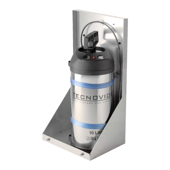
- Page 3 CCTV cameras in industrial, marine and highly corrosive environments. The washer system supplied pairs preferably with Tecnovideo camera housings or alternatively with housings which haven't washer facility. The fluid tank is a 10 litre manually pressurized unit with built in pressure gauge. Solenoid's control voltage to be connected to the solenoid's terminal box through suitable power cables.
- Page 4 Before performing any operation, turn off the power. The installation of the unit can be performed only by qualified personnel in accordance with the regulations in force. Do not connect the unit to a supply circuit unless the installation is completed.
- Page 5 INSTALLING THE UNIT Opening the washer system Loosen the two M6 screws to remove the cover and to access the internal parts. Do not remove the screws. Screws Passing the cables There are 5 fairleads placed 2 at the bottom and 3 on the side of the frame.
- Page 6 O-ring seals. Replace them if necessary. Check tank, hand pump and pressure gauge integrity. If any damage is noticed, please contact Tecnovideo for spare parts. Check cables, electrical connections and mounting hardware for integrity and tightness. Replace or tighten any damaged/loose part.
- Page 7 ELECTRICAL DIAGRAM In the diagram below it is shown how to control WP10EX Series washer systems via a Dry Contact Relay input. To do so, it is needed the DCI-EXWP interface (sold separately).
- Page 8 Check carefully the attached Solenoid valve "Operating Instructions": in case of doubt, refer to that document. TECNOVIDEO S.r.l. Via A. De Gasperi, 3 36030 Villaverla (VI) ITALY Tel. +39.0445.350444 Fax +39.0445.357259...
Need help?
Do you have a question about the WP10EX Series and is the answer not in the manual?
Questions and answers