Table of Contents
Advertisement
Advertisement
Table of Contents

Related Manuals for ALL-TEST PRO MOTOR GENIE

Summary of Contents for ALL-TEST PRO MOTOR GENIE
- Page 1 ALL-TEST Pro, LLC MOTOR GENIE ©2016, ALL-TEST Pro, LLC Rev 2016-10...
-
Page 2: Table Of Contents
Additional Data Interpretation Considerations Three Phase Motors .....25 Test Location ....................26 Confirming Suspected Winding Shorts ............26 Method 1: Rotor Compensation ..............26 Method 2: Variable Frequency Test ..............27 IV. Available Accessories for the MOTOR GENIE™ ........29 XI. Disclaimer, Copyright & Trademarks ............31 ©2016, ALL-TEST Pro, LLC Rev 2016-10... -
Page 3: Introduction
Insulation Resistance to ground: To prevent electrical shocks and to assure safety of personnel the MOTOR GENIE™ provides an insulation to ground test. The insulation resistance test provides either 500 or 1,000 V to measure the insulation resistance up to 500 Meg-Ohm. -
Page 4: Safety
Attaching the MOTOR GENIE to live voltage will destroy the unit and void the warranty. Do not attempt to change the batteries. Contact your distributor of the MOTOR GENIE , ALL- TEST Pro, LLC at 860-399-4222 or via email (support@alltestpro.com), to have the battery pack replaced. -
Page 5: Instrument Operation
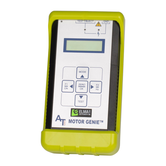
The instrument is divided up into three working areas: 1. Input Section 2. Display Area 3. Keypad Input Section The input section provides all the external connections to the MOTOR GENIE A. Test lead port B. Charger port C. Ground test lead port for Insulation to Ground Measurements D. -
Page 6: Display Section
The display screen has individual icons to select and perform the various motor and winding tests. 1. Z/ψ Icon performs the Impedance (Z), Phase Angle (ψ), Current/Frequency (I/F) and Phase Balance tests (used to identify developing winding faults). www.alltestpro.com ©2016, ALL-TEST Pro, LLC Rev 2016-10... - Page 7 – see the highlighted part below. 6. Battery charge level indicator. A fully charged battery will have 7 bars (it is recommended to keep the AT31 on charge when not in use to ensure proper operation). www.alltestpro.com ©2016, ALL-TEST Pro, LLC Rev 2016-10...
-
Page 8: Keypad Section
Instrument Test Leads The MOTOR GENIE uses a 15-pin DB connector for winding testing. The red test lead is the output and the black test lead, is the return. For insulation testing, the yellow test lead should be connected to ground. -
Page 9: Testing A Three Phase Induction Squirrel Cage Motor
IV. Testing a Three Phase Induction Squirrel Cage Motor Testing can be performed remotely from the motor control center, the motor disconnect or at the motor itself. This instruction is provided to demonstrate all of the features of the MOTOR GENIE , which can also be used to evaluate other types of electric machines. -
Page 10: Turn The Instrument On
Display screen 1: Displays the measured impedance in ohms 107, phase angle in degrees 66 , and the frequency of the winding test, 200 Hz. The screen number (1) is displayed in the upper left hand corner. Display Screen 1 www.alltestpro.com ©2016, ALL-TEST Pro, LLC Rev 2016-10... -
Page 11: Error Codes
--- means either the impedance or resistance value is over 60,000 Ω, or the test is invalid. Continue with Other Phases 1. Move the test leads to T1 & T3 to make the measurements on the next phase. www.alltestpro.com ©2016, ALL-TEST Pro, LLC Rev 2016-10... - Page 12 2. Read the Impedance (Z) and Phase Angle (ψ) values from display screen 1 for winding. Do not fill in the phase balance until all three phases have been measured. 3. Depress the TEST key to display the Current Frequency Response (I/F). Winding 2 Current Frequency Response www.alltestpro.com ©2016, ALL-TEST Pro, LLC Rev 2016-10...
-
Page 13: Continue With Last Phase
Phase Angle (°) Z-Test or I/F Resistance (Ω) Phase balance (opt) Test Ins Resistance (M Ω) Voltage Comments: ©2016 ALL-TEST Pro, LLC Continue with Last Phase 1. Move the Test Leads to T2 & T3 www.alltestpro.com ©2016, ALL-TEST Pro, LLC Rev 2016-10... - Page 14 Test Date: 8/8/16 Test Frequency 200 Hz Phase Phase Phase Impedance (Z) Phase Angle (°) Z-Test or I/F Resistance (Ω) Phase balance (opt) Test Ins Resistance (M Ω) Voltage Comments: ©2016 ALL-TEST Pro, LLC www.alltestpro.com ©2016, ALL-TEST Pro, LLC Rev 2016-10...
-
Page 15: Resistance Test
Note: for poor connection or no connection, the following screen will show up for a couple of seconds and resume to the right screen above. In such case, please check the connections and press ZERO/OK key again. No continuity means the circuit is open. www.alltestpro.com ©2016, ALL-TEST Pro, LLC Rev 2016-10... - Page 16 Phase balance (opt) Test Ins Resistance (M Ω) Voltage Comments: ©2016 ALL-TEST Pro, LLC 7. To exit to the main menu, press the MODE key. Note: To make resistance measurement again, repeat Steps 1 ~ 7 above. www.alltestpro.com ©2016, ALL-TEST Pro, LLC...
-
Page 17: Phase Balance Test
This calculates the impedance unbalance between phases. This value can be used to relate energy, reliability and production-cost avoidance potential to electric motor systems impedance unbalance. The Impedance Unbalance Calculator (IUC) is available from ALL-TEST Pro. The concept of the IUC comes from Keeping the Spark in Your Electrical System: An Industrial Electrical Distribution Maintenance Guidebook published by the US Department of Energy, Bonneville Power Administration, Pacific Gas &... - Page 18 Record this number on the Motor Test Data form. Note: The percentage should be less than 3% of phase unbalance. A percentage > 5% indicates a fault in the winding and should be investigated further www.alltestpro.com ©2016, ALL-TEST Pro, LLC Rev 2016-10...
- Page 19 Test Frequency 200 Hz Phase Phase Phase Impedance (Z) Phase Angle (°) Z-Test or I/F Resistance (Ω) 17.3 17.6 17.1 Phase balance (opt) Test Ins Resistance (M Ω) Voltage Comments: ©2016 ALL-TEST Pro, LLC www.alltestpro.com ©2016, ALL-TEST Pro, LLC Rev 2016-10...
-
Page 20: Insulation Resistance Testing
MOTOR GENIE User Manual Insulation Resistance Testing To prevent electrical shocks and to assure safety of personnel the MOTOR GENIE provides an insulation to ground test. The insulation resistance test provides either 500 or 1,000 V , to measure the insulation resistance up to 500 Meg-Ohm. - Page 21 Test Frequency 200 Hz Phase Phase Phase Impedance (Z) Phase Angle (°) Z-Test or I/F Resistance (Ω) 17.3 17.6 17.1 Phase balance (opt) Test Ins Resistance (M Ω) >500 Voltage Comments: Comments: ©2016 ALL-TEST Pro, LLC www.alltestpro.com ©2016, ALL-TEST Pro, LLC Rev 2016-10...
-
Page 22: Changing The Motor Test Frequency
User Manual Changing the Motor Test Frequency The default testing frequency for the MOTOR GENIE is set at 200 Hz. This test frequency should be good for the majority of winding tests. However, there are some instances where a different frequency may be required. -
Page 23: Additional Functions And Features
V. Additional Functions and Features Resetting the Unit On occasion, the MOTOR GENIE may fail to respond to keyboard, or lock up due to excessive EMI present or other reasons. Sometimes the unit may lock up during normal operation. To reset the unit if it locks up, simply PRESS the reset button (highlighted below in yellow) using a paper clip, pen tip or some other small device. -
Page 24: Charging The Motor Genie
If the supplied charger becomes lost or defective contact ALL-TEST Pro sales support for a replacement. The installed batteries are not subject to retain memory. To ensure the MOTOR GENIE being fully charged, leave it plugged into the charging unit when not in use. A fully charged battery should last about 8 hours. -
Page 25: Data Interpretation Three Phase Motors
> 1 Meg-Ohm + 1 Meg-Ohm per kV rating of motor Random Wound motors less than 600 V > 5 MegOhms Additional Data Interpretation Considerations Three Phase Motors There are additional considerations when using an MOTOR GENIE Test location Confirming winding faults www.alltestpro.com ©2016, ALL-TEST Pro, LLC... -
Page 26: Test Location
If a fault is detected when testing from the motor control center, motor disconnect, or from any distance away from the motor through cabling, it is important that a confirmation test be performed at the motor connection box prior to condemning a winding. Note: ALL-TEST PRO MCA™ instruments will detect cable faults. -
Page 27: Method 2: Variable Frequency Test
Table 6, the Fi values changed from 70 to 75. Then the spread has increased to 5 units. This winding should be considered to be in poor condition. Table 6: Adjusted Frequency Sample, Bad T1-T2 T1-T3 T2-T3 www.alltestpro.com ©2016, ALL-TEST Pro, LLC Rev 2016-10... - Page 28 MOTOR GENIE User Manual www.alltestpro.com ©2016, ALL-TEST Pro, LLC Rev 2016-10...
-
Page 29: Available Accessories For The Motor Genie
MOTOR GENIE User Manual VIII. Tech Support and Information Technical support can be obtained by emailing or faxing your questions to ALL-TEST Pro, LLC at: Email: support@alltestpro.com Fax: 860-399-3180 Please put “MOTOR GENIE Tech Support” in your subject line. IV. Available Accessories for the MOTOR GENIE™... - Page 30 Phase Impedance (Z) Phase Angle (°) Z-Test or I/F Resistance (Ω) Phase balance (opt) Test Ins Resistance (M Ω) Voltage Comments: ©2016 ALL-TEST Pro, LLC MOTOR GENIE Motor Test Form Motor ID: Location: Test Date: Test Frequency Phase Phase Phase Impedance (Z) Phase Angle (°)
-
Page 31: Disclaimer, Copyright & Trademarks
Nothing contained herein shall be construed as conferring by implication or otherwise any license or right under any patent or trademark of ALL-TEST Pro, LLC or any third party. No other rights under any copyrights of ALL-TEST Pro, LLC or any other party are granted herein, except as expressly stated above.
Need help?
Do you have a question about the MOTOR GENIE and is the answer not in the manual?
Questions and answers