Table of Contents
Advertisement
Quick Links
Operating instructions
Technical description
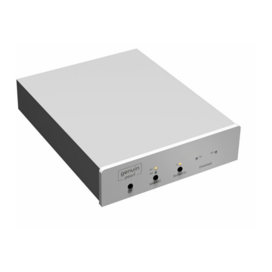
pearl
Phono preamplifier with external power supply
Scope of delivery
1 x Phono preamplifier pearl
1 x Power supply for phono preamplifier pearl
1 x Connecting cable phono preamplifier pearl > power supply
1 x Mains cable for power supply
Putting into operation
Please first establish the connections between pearl and turntable and amplifier
respectively as well as the connection to the external power supply and the local power
grid* - see the following chapter "Connecting". Only then switch on the power supply and
the phono preamplifier. Please do not remove any connection cables during ongoing
operation - but switch off the phono preamplifier as well as the power supply beforehand.
When connecting the device for the first time as well as after switching on the external
power supply, the output of the phono preamplifier is blocked for approx. 30 seconds.
During this time, internal servo circuits adjust themselves so that there is no DC voltage at
the output. After accomplishing that, the phono preamplifier switches on immediately.
Since the device has a long warm-up phase until it reaches its full sonic potential, it should
be operated with the power supply permanently switched on. The power consumption is
less than 11 watts. All internal amplification sections work in Class A mode.
* Note: Before connecting this unit to the mains power using the power supply cable, you must ensure that the
unit's mains voltage setting matches the local mains voltage. If you are unsure and have any questions about the
local power supply, please contact your local electricity supplier. The device operates with 230 V.
Advertisement
Table of Contents

Related Manuals for Genuin Audio Pearl

Summary of Contents for Genuin Audio Pearl
- Page 1 1 x Mains cable for power supply Putting into operation Please first establish the connections between pearl and turntable and amplifier respectively as well as the connection to the external power supply and the local power grid* - see the following chapter "Connecting". Only then switch on the power supply and the phono preamplifier.
- Page 2 Please refer to the schematic illustration on the bottom of the device for the assignment of the rear inputs and outputs. Cables with a length of up to 4 meters can be connected to the output sockets of the pearl, since significant interaction between cable capacitance and output resistance are negligible due to the low output resistance of less than 50 Ohms.
- Page 3 Cartridge operation The pearl phono preamplifier basically allows the use of Moving Magnet (MM), Moving Iron (MI) and Moving Coil (MC) cartridge systems, the latter also in the "high output" variant. The pearl phono preamplifier provides simultaneous operation of two cartridges. One cartridge must always be an MC system, while the other can be an MM or MI system.
- Page 4 Overload indication Two red LEDs on the front panel signal a massive overload of the device - accompanied by a very high output level. Possible causes: the unintentional connection of an MM cartridge to the MC input, incorrect wiring or the erroneous connection to the output of a high-output level device.
- Page 5 125 Ohms MC gain The Gain slide switches change the gain of the MC stage. The overall gain of the pearl phono preamplifier is always the sum of both MC and MM gains. When the switches are not operated, the MC gain is 20 dB.
- Page 6 +47 pF Thus, the maximum load capacitance when using the above mentioned exemplary tonearm genuin audio point is 285 pF (= 5 x 47 pF pearl + 50 pF inherent capacitance tonearm). MM gain The Gain slide switches allow gain adjustment of the MM amplifier section.
- Page 7 In case of mismatch and possibly resulting overload, the two LEDs "Overload" on the front panel flash red. The overload limits for MM and MC referred to 1 kHz are + 20 dB above nominal level. The nominal levels for MC and MM are 0.5 mV and 5 mV respectively. Specifications Input impedance MM……………………………………………………………….……..…47 kOhms Input impedance MC………………………………………..variable from 125 Ohms to 2 kOhms...
- Page 8 No part of this manual may be reproduced, transmitted in any form or by any means, electronically, mechanically, by photocopying or recording, without the prior written permission of genuin audio.
Need help?
Do you have a question about the Pearl and is the answer not in the manual?
Questions and answers