Advertisement
M
. W
R
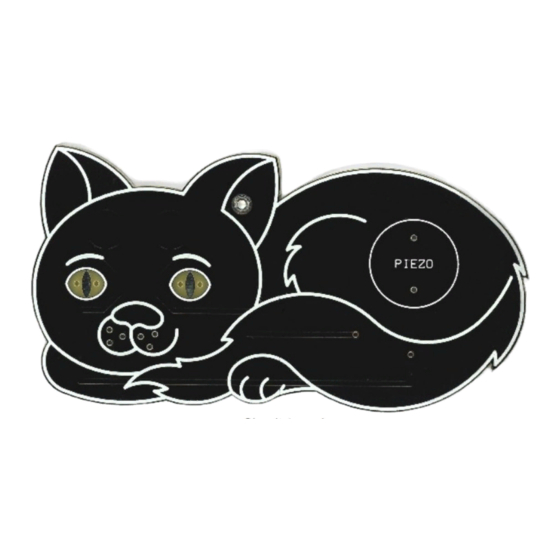
HISKERS
a badge that meows
R1
R2
L1
(150R)
(150R)
(yellow)
(yellow)
Circuit board
Piezo
Coin cell retainer
Wire
IC1
PIC12F1840
C1
L2
10u electrolytic
Socket
Butterfly clip and pin
Identify the different components using the spotter chart.
1
Solder the resistors to the pads on the back side of the circuit board such that
2
they fit within their symbols (R1 and R2). Clip their legs close to the solder
joints. They can be fitted either way around. See image overleaf.
Fit the capacitor to the board within its symbol (C1) and solder the shorter leg
3
to the pad with the – sign. Solder the other leg to the other pad then clip both
legs. The shorter leg also has a stripe on the side of the body.
Bend the legs of the chip socket outwards at right angles then solder it to the
4
back side of the board matching the notch in the socket to the notch in the
symbol (IC1). Solder one corner pin first, check the alignment then solder the
other pins. Do not solder the chip directly to the board. Then carefully bend
the legs of the chip inwards a little with your fingers and fit it into its socket
matching the small notch in the chip to the notch in the socket.
Add a small blob of solder to the middle of the large metal square on the back
5
side of the board to help make a better connection with the coin cell. Spread the
solder around a little with the soldering iron so it is not too high then fit the coin
cell retainer to this side of the board matching the marked outline. Solder the
two tabs to the board using plenty of solder to make the joints physically strong.
Either fit the lights (L1 and L2) to the front side of the board in the conventional
6
manner, or bend their legs through 180 degrees and fit them to the back of the
board so that their light shines through the material (see close-up overleaf). In
either case put the shorter leg into the hole marked with a 'k'. Bend the legs
away from each other and solder them to the back of the board. Clip the legs
short.
Fit the speaker (PIEZO) to the front of the board and solder it on the back.
7
Cut the solid wire into 6 equal length pieces, strip the insulation from one end
8
and solder them to the holes in the face to form the whiskers.
Insert a CR2032 coin cell into the retainer with the positive (+) side
9
uppermost. The lights should flash and it should beep twice.
Fit the pin through the hole at the top of the board and then through your
10
clothing. Use the butterfly clip to hold your badge securely in place. The
pin can be soldered in place if you wish.
HOW TO USE
Stroke Mr. Whisker's head and he will meow and flash his eyes.
Remove the coin cell when not using the badge for any length of time.
© MadLab® 2019
www.madlab.org
1/6/19
Advertisement
Table of Contents

Related Manuals for MadLab MR. WHISKERS


Summary of Contents for MadLab MR. WHISKERS
- Page 1 Butterfly clip and pin Piezo Coin cell retainer HOW TO USE Stroke Mr. Whisker’s head and he will meow and flash his eyes. Remove the coin cell when not using the badge for any length of time. Wire © MadLab® 2019 www.madlab.org 1/6/19...
Need help?
Do you have a question about the MR. WHISKERS and is the answer not in the manual?
Questions and answers