
Subscribe to Our Youtube Channel
Summary of Contents for HYDAC FILTER SYSTEMS CMP1000 Series
- Page 1 CMP 1000 series ConditionMonitoring Package Installation and Maintenance Instructions English (translation of original instructions) Documentation no.: 3528418d...
-
Page 2: Imprint
+49 (0)6897 509 1394 E-Mail: guenter.harge@hydac.com © HYDAC FILTER SYSTEMS GMBH All rights reserved. No part of this work may be reproduced in any form (print, photocopy or by other means) or processed, duplicated or distributed using electronic systems without the written consent of the publisher. -
Page 3: Table Of Contents
Content Content Imprint......................2 Documentation Representative ..............2 Content ......................3 Preface......................5 Technical Support..................5 Modifications to the Product ................5 Warranty ......................5 Using the documentation ................6 General Safety Information ................7 Hazard symbols...................7 Signal words and their meaning in the safety information and instructions ....................8 Structure of the safety information and instructions........9 Observe regulatory information ..............9 Proper/Designated Use ................10... - Page 4 Content Hydraulic connectors .................24 Notes on pipes and hoses .................25 Connecting the suction port connection - IN...........26 Connecting the return port connection - OUT.........27 Overload protection (only with CMP1xx0-4…)........27 Electrical connection of the CMP ..............28 Electrical connection of the ContaminationSensor CS1000.......29 Electrical connection of the AquaSensor AS1000 ........29 Starting up the CMP..................30 Required tools and measuring instruments ..........30...
-
Page 5: Preface
Warranty For the warranty provided by us, please refer to the General Terms of Sale and Delivery of HYDAC FILTER SYSTEMS GmbH. You'll find this under www.hydac.com -> General terms and conditions. CMP1000... -
Page 6: Using The Documentation
Preface Using the documentation Note that the method described for locating specific information does not release you from your responsibility of carefully reading these instructions prior to starting the unit up for the first time and at regular intervals in the future. WHAT do you want to know? I determine which topic I am looking for. -
Page 7: General Safety Information
General Safety Information General Safety Information The unit was built according to the statutory provisions valid at the time of delivery and satisfies current safety requirements. Any residual hazards are indicated by safety information and instructions and are described in the operating instructions. Observe all safety and warning instructions attached to the unit. -
Page 8: Signal Words And Their Meaning In The Safety Information And Instructions
General Safety Information Risk of burns due to hot surfaces Signal words and their meaning in the safety information and instructions DANGER DANGER indicates a danger with a high risk and which will lead to death or serious injury if not avoided. WARNING WARNING indicates a danger with a medium risk and which can lead to death or serious injury if not avoided. -
Page 9: Structure Of The Safety Information And Instructions
General Safety Information Structure of the safety information and instructions All warning instructions in this manual are highlighted with pictograms and signal words. The pictogram and the signal word indicate the severity of the danger. Warning instructions listed before an activity are laid out as follows: SIGNAL WORD Type and source of danger HAZARD SYMBOL... -
Page 10: Proper/Designated Use
General Safety Information Proper/Designated Use Use the unit only for the application described in the following. The ConditionMonitoring Package CMP is for the continuous monitoring of solid particle contamination in hydraulic systems. Proper or designated use of the product extends to the following: ... -
Page 11: Improper Use Or Use Deviating From Intended Use
► media. Any use extending beyond or deviating therefrom shall not be considered intended use. HYDAC Filter Systems GmbH will assume no liability for any damage resulting from such use. The user alone, shall assume any and all associated risk Improper use may result in hazards and/or will damage the unit. -
Page 12: Qualifications Of Personnel / Target Group
General Safety Information Qualifications of personnel / target group Persons who work on the power unit must be aware of the associated hazards when using the power unit. Auxiliary and specialist personnel must have read and understood the operating instructions, in particular the safety information and instructions, and applicable regulations before beginning work. - Page 13 General Safety Information Knowledge with regard to recycling CMP1000 Page 13 / 44 en(us) MoWa CMP 3528418d en-us 2015-01-06.doc 2015-01-06...
-
Page 14: Wear Suitable Clothing
General Safety Information Wear suitable clothing Loosely worn clothing increases the danger of getting caught or wound up in rotating parts and the danger of getting snagged on projecting parts. You can be severely injured or killed. Wear close-fitting clothing. ... -
Page 15: Unpacking The Unit
Unpacking the unit Unpacking the unit The CMP is inspected for leaks and proper functioning at the factory, then carefully packed for shipment. The connectors are closed off so that no contamination can enter the unit while it is in transit. When receiving and unpacking the unit, check it for damage in transit. -
Page 16: Decoding The Model Code Label
Decoding the model code label Decoding the model code label Details for identifying the power unit can be found on the type labels on the unit and the components. Item -> Description -> Power unit type label -> Name plate of electric motor ->... -
Page 17: Checking The Scope Of Delivery
Checking the Scope of Delivery Checking the Scope of Delivery Upon receiving the CMP check it for any damage in transit. Do not put the CMP into operation unless it is in perfect condition. Report any damages in transit to the transport company or the responsible agent immediately. Do not put the unit into operation. -
Page 18: Cmp Features
CMP Features CMP Features The gear pump sucks the oil to be analyzed and conveys it to the Contamination Sensor, in which the particulate contamination is captured by an optical sensor and analyzed according to particle size classifications and counted. Any air bubbles contained in the oil may skew the measurement results as they, like particulate contamination, cause the measurement cell to generate signals. -
Page 19: Cmp Components
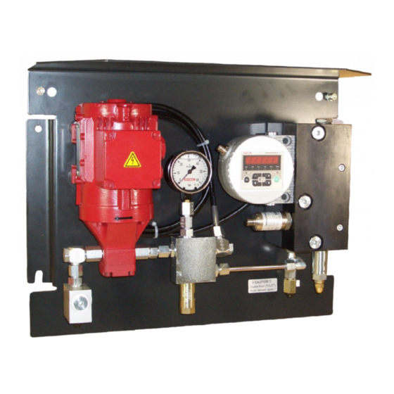
CMP Components CMP Components Item Designation Electric motor Gear pump Pressure relief valve Counter balance valve ConditionSensor CS1000 series Suction strainer, 400 µm Suction port (IN) Return port connection (OUT) AquaSensor AS1000 Pressure gauge CMP1000 Page 19 / 44 en(us) MoWa CMP 3528418d en-us 2015-01-06.doc 2015-01-06... -
Page 20: Cmp1Xx0-2-1
CMP1xx0-2-1 … hydraulic schema CMP1xx0-2-1 … hydraulic schema Item Designation Electric motor Gear pump Pressure relief valve Counter balance valve ConditionSensor CS1000 series Suction strainer, 400 µm Suction port (IN) Return port connection (OUT) AquaSensor 1000 Pressure gauge CMP1000 Page 20 / 44 en(us) MoWa CMP 3528418d en-us 2015-01-06.doc 2015-01-06... -
Page 21: Cmp1Xx0-4-1
CMP1xx0-4-1 … hydraulic schema CMP1xx0-4-1 … hydraulic schema Item Designation Electric motor Gear pump Pressure relief valve Counter balance valve ConditionSensor CS1000 series Suction strainer, 400 µm Suction port (IN) Return port connection (OUT) AquaSensor 1000 Pressure gauge CMP1000 Page 21 / 44 en(us) MoWa CMP 3528418d en-us 2015-01-06.doc 2015-01-06... -
Page 22: Cmp1Xx0-2-1
CMP1xx0-2-1 … dimensions CMP1xx0-2-1 … dimensions CMP1000 Page 22 / 44 en(us) MoWa CMP 3528418d en-us 2015-01-06.doc 2015-01-06... -
Page 23: Cmp1Xx0-4-1
CMP1xx0-4-1 … dimensions CMP1xx0-4-1 … dimensions CMP1000 Page 23 / 44 en(us) MoWa CMP 3528418d en-us 2015-01-06.doc 2015-01-06... -
Page 24: Hydraulic Connection Of The Cmp
Hydraulic connection of the CMP Hydraulic connection of the CMP Hydraulic connectors CMP1xx0-2 CMP1xx0-4 Suction port connection Return port connection CMP1000 Page 24 / 44 en(us) MoWa CMP 3528418d en-us 2015-01-06.doc 2015-01-06... -
Page 25: Notes On Pipes And Hoses
Hydraulic connection of the CMP Notes on pipes and hoses In order to keep the pressure loss as low as possible, use as few threaded connections as possible. The pressure loss in a hydraulic line depends upon: Flow rate ... -
Page 26: Connecting The Suction Port Connection - In
Hydraulic connection of the CMP Connecting the suction port connection - IN NOTICE Overpressure at the suction port connection (IN) The unit will be destroyed Note the maximum pressure on the suction port connection IN ► for CMP1xxx-2 = -0.4 bar … 80 bar for CMP1xxx-4 = -0.4 bar …... -
Page 27: Connecting The Return Port Connection - Out
Hydraulic connection of the CMP Connecting the return port connection - OUT NOTICE Return port connection (OUT) closed off The unit will be destroyed Make sure that the return port is always open ► CMP 1xx0-2 ► Note the maximum pressure of 0.5 bar at the return port connection CMP 1xx0-4 ►... -
Page 28: Electrical Connection Of The Cmp
Electrical connection of the CMP Electrical connection of the CMP DANGER Exposed electrical components in the switch cabinet Danger of fatal injury due to electric shock Any work involving the electrical system may ► only be done by a properly trained, certified electrician. -
Page 29: Electrical Connection Of The Contaminationsensor Cs1000
Electrical connection of the CMP Electrical connection of the ContaminationSensor CS1000 For more information, refer to the ContaminationSensor operating and maintenance instructions included. Electrical connection of the AquaSensor AS1000 For more information, refer to the AquaSensor operating and maintenance instructions included. CMP1000 Page 29 / 44 en(us) -
Page 30: Starting Up The Cmp
Starting up the CMP Starting up the CMP You must adjust the counter balance valve (1) once the CMP has been connected hydraulically to the entire system with IN/OUT and once and the electrical connection has been completed. This is described on page 31. The counter balance valve (1) is completely open at the time the unit is shipped. -
Page 31: Adjusting The Counter Balance Valve
Adjusting the counter balance valve Adjusting the counter balance valve Set the counter balance valve (1) in accordance with the following steps: Switch the unit on. Check the suction intake behavior of the pump and the oil flow. If a uniform volume flow can be heard via the noise of the pump or if it can be detected on the outlet side (OUT), the pressure... - Page 32 Adjusting the counter balance valve from the viscosity and the hydraulic resistance. Unscrew the head-nut from the counter balance valve (1). Release the lock nut on the counter balance valve (1). Set the pressure for a maximum operating medium viscosity to 25 ...
- Page 33 Adjusting the counter balance valve Tighten the lock nut. Make sure that the setting of the counter balance valve (1) is not changed in the process. Screw the head-nut onto the counter balance valve and tighten it firmly. The CMP is now ready for operation.
-
Page 34: Performing Maintenance
Performing Maintenance Performing Maintenance WARNING Operating pressure Danger of bodily injury The hydraulic system must be depressurized ► before performing any work on the hydraulic system. The prescribed adjustment, maintenance/servicing and inspection work is to be conducted in accordance with the respective schedules. The Unit is to be disconnected from the power supply and protected against being inadvertently switched back on when performing any maintenance, servicing, inspection or repair work. -
Page 35: Clean The Suction Strainer
Performing Maintenance Clean the suction strainer NOTICE Suction strainer missing / operating without a suction strainer The unit will be destroyed Never operate the unit without a suction strainer. ► Clean the suction screen regularly. ► A suction strainer is fitted into a piece of pipe of the suction line to protect the pump from coarse contamination. - Page 36 Performing Maintenance 3. Clean the suction strainer by washing it out and then blowing it out with compressed air. 4. Rotate the suction strainer in clockwise direction into the housing with a large, flat screwdriver. 5. Screw in the screw plug by hand and tighten it with 12 Nm.
-
Page 37: Errors And Troubleshooting
Errors and troubleshooting Errors and troubleshooting Error Cause(s) Remedy No flow rate The pump is conveying in Check the direction of the wrong direction. rotation of the motor, if necessary change the phases in the supply line. Shut-off device outside of Open the shut-off device. -
Page 38: Spare Parts List
Spare parts list Spare parts list Item Part no. Qty. Description Material 3152786 Suction strainer, 400 µm ContaminationSensor CS1000 3281243 Connecting socket, M12x1, 8-pin 6006786 Connecting socket, M12x1, 5-pin AquaSensor AS 1000 Motor pump assembly * = on request Disposing of the unit After dismantling the unit and separating the various materials, dispose of the unit in an environmentally-friendly manner. -
Page 39: Technical Details
Technical details Technical details General data Hydraulic fluid temperature 0 … 70°C / 32 … 158°F ambient temperature 0 … 50°C / 32 … 122°F Storage temperature -40°C … 80°C / -40°F … 176°F Relative humidity max. 90%, non-condensing Weight CMP1xx0-2 ~25 kg CMP1xx0-4... - Page 40 Technical details Electrical data CSM1xxx-2-x-W/N/X60/O60 Voltage (delta circuit) 230 V, 50 Hz, 3 Ph 265 V, 60 Hz, 3 Ph Voltage (Star (Y-) connection) 400 V, 50 Hz, 3 Ph 460 V, 60 Hz, 3 Ph 1.23 A / 0.71 1.18 A / 0.68 Current consumption...
-
Page 41: Model Code
Model Code Model Code 0 - 2 - 1 N/AB/N60/AB6 Type = ConditionMonitoring Package Version = 4 particle size channels Contamination code = ISO4406:1999, SAE AS 4059(D) / >4 µm >6 µm , 14 µm >21 µm = ISO4406:1987, NAS1638 / >2 µm >5 µm >15 µm >... -
Page 42: Index
Index Index ISO4406 ............... 41 1987 ................. 41 1999 ................. 41 AquaSensor......4, 19, 20, 21, 29, 38, 41 Auxiliary personnel ..........12 Maintenance..........1, 4, 17, 34 measuring............4, 30 Mineral oil ............. 25 Model code............16 Calibration ............17 Cause ..............37 connecting ............ - Page 43 Index Weight .............16, 39 CMP1000 Page 43 / 44 en(us) MoWa CMP 3528418d en-us 2015-01-06.doc 2015-01-06...
- Page 44 HYDAC FILTER SYSTEMS GMBH Industriegebiet Postfach 1251 66280 Sulzbach/Saar 66273 Sulzbach/Saar Germany Germany Phone: +49 (0) 6897 509 01 Central Fax: +49 (0) 6897 509 9046 Technical Department Fax: +49 (0) 6897 509 577 Sales Department Internet: www.hydac.com Email: filtersystems@hydac.com...
Need help?
Do you have a question about the CMP1000 Series and is the answer not in the manual?
Questions and answers