
Subscribe to Our Youtube Channel
Related Manuals for TEA TMM-100

Summary of Contents for TEA TMM-100
- Page 1 TMM-100 Temperature Measurement Module Operating Manual Thermal Engineering Associates, Inc. 3287 Kifer Road Santa Clara, CA 95051 USA Tel: 1-650-961-5900 Fax: 1-650-227-3814 E-mail: info@thermengr.com Revision 4...
-
Page 2: Table Of Contents
Applying the data from the test die to a func- tional system is the responsibility of the user. TEA makes no warranty, expressed or implied including the implied warranties of merchantability and fitness for a particular purpose, that the user's system designed using that data will perform as intended by the user. - Page 3 TMM-100 INTRODUCTION DESCRIPTION The TMM-100 is designed to simplify the gathering of temperature data from eight Thermal Test Chip diode temperature sen- sors. The system contains precision current sources for supplying diode measurement current (I ), voltmeter capability for diode measurement (V ), and Type-T thermocouple and 10KΩ...
- Page 4 TMM-100 INTRODUCTION SPECIFICATIONS Diode Current Source Number of Channels Measurement Current 1.00mA Accuracy 0.1% Voltage compliance 1.999V Polarity - or + to GND Connection Front Panel, IDC Ribbon Cable Connector Diode Voltage Measure Number of Channels 8 (integrated with Current Source) Range 1.999V...
-
Page 5: Introduction
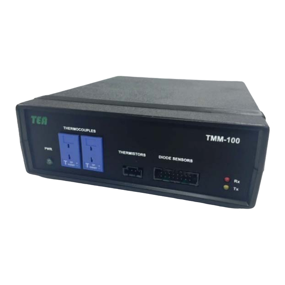
GETTING STARTED Unpack Your Module Your box should contain the following items: TMM-100 Temperature Measurement Module USB 2.x Cable (Type A on one end, Type B on other end) Combination Diode/Thermistor Sensors connection cable Type-T #36 Gauge Thermocouples with mating connectors ... - Page 6 Before you cable your router, take a moment to become familiar with the label and the front and back panels. Pay particular attention to the LEDs on the front panel. Module Front Panel The TMM-100 front panel has: Green Power LED Red LED for USB Tx Data ...
-
Page 7: Operation
Retry button. After a few more seconds, the con- nection indicator will turn green and the COM port ac- tually used will appear in the COM port box. Figure 2-2 Missing Module Message The TMM-100 is now ready for use. TMM-100_User_Manual_r4.doc Rev4... - Page 8 TMM-100 OPERATION TMM-100 Operating Screen is divided into several sections: Communications Status Located in the top right (see Figure 2-1). This section con- tains the COM port box and COM port status indicator. Immediately below are the status indicators data READ and SCAN.
- Page 9 TMM-100 OPERATION The Diode Temperature Sensor data is in terms of millivolts (mV) or de- grees centigrade (ºC), as determined by the slide control below the diode selection column. In order for the di- ode results to be in centigrade, the...
- Page 10 Immediately below the Sample Rate control is the entry box for the datafile path and file- name. If the TMM-100 is running on a Windows XP Pro computer, then the full path and filename must be entered here in order to save the data file.
- Page 11 TMM-100 OPERATION Data Display In the TIMED SCAN mode, the collected data is shown near the bottom of the screen in either tabular form, as shown in Figure 2-8, or in chart form, shown Figure 2-9. The tabs at the...
- Page 12 TMM-100 OPERATION Diode Calibration In order for the diode temperature sensors to produce readings in units of ºC, the diode volt- age must be correlated to temperature. The DIODE SENSOR CALIBRATION routine per- forms this function. The steps to using this routine are as fol-...
- Page 13 TMM-100 OPERATION To cease operation of the TMM-100 software, click on the QUIT button at the lower right of the screen. The unit can be left connected (the front panel green indicator will remain on) to the computer but will be inactive until the TMM-100 program is again loaded and run.
-
Page 14: Applications
APPLICATIONS Electrical Connections The TMM-100 unit is supplied with cables and thermocouples to facilitate user connection to the various temperature sensors measured by the unit. The user is responsible for making the electrical connection between the unit and sensors according to the schematic shown in Figure 3-1. - Page 15 6944-1-ND] or equivalent, is a small chip that can be mounted to a printed circuit board near a heat source without impacting air flow. A Fan Control cable is also supplied with the TMM-100. Two alternative wiring configurations are shown in Figure 3-2. The relay load capability should be limited to <50V and <0.5A.
- Page 16 TTC-1002 0.5046ºC/mV The TMM-100 supplies 1mA to each of the diodes connected and measures the voltage for each of the diodes selected (see Figure 2-8). The diode voltage will decrease as the sensor heats up. The diode voltage value at equilibrium before heating occurs minus the diode volt- age at a specified time during the heating produces a voltage difference that is multiplied by the K Factor to produce a temperature difference.
- Page 17 TMM-100 APPLICATIONS 2) Connect up the power supply and measurement equipment shown in the Apparatus Setup. 3) Apply the 1.0mA Measurement Current to the diodes used for temperature measurement. 4) Wait for thermal equilibrium to occur - i.e., when the diode voltages stop changing - to re- cord the diode voltage.
-
Page 18: Installation
TMM-100 INSTALLATION The software for installing and running the TMM-100 is supplied on a USB Flash Drive. The steps for installing the software on Windows 7.x or Windows 8.x operating system computer is de- scribed below. Step 1. Connect the supplied USB Ca- ble into the TMM-100 rear panel;... - Page 19 Step 8. With the installation complete, the last step is to create a desktop icon for easy ac- cess to the TMM-100 software. Follow the procedure normally used to create a desktop icon. The TMM-100 can now be connected to the computer. Plug the cable into a computer USB port and open the TMM-100 software.
- Page 20 TMM-100 Accessories Diode/Thermistor Cable Assembly (TEA PN: 985-00801-000) Thermocouples (TEA PN: 680-00002-001) Type-T #36 gauge 3-feet long (Omega Engineering (SC-TT-T-36-36) TMM-100_User_Manual_r4.doc Rev3...
- Page 21 TMM-100 Accessories Fan Control Cable Assembly (TEA PN: 985-00802-000) TMM-100_User_Manual_r4.doc Rev3...
-
Page 22: Warranty & Repair
TEA will cause the WARRANTY to become null and void. Product failure(s) caused by neglect, misuse, weather, shipping damages, acts of war, act of God, or other acts not under control of TEA render the WARRANTY inapplicable. - Page 23 The customer will pre- pay shipment of the product back to TEA and agrees to accept return of the repaired or replaced product via shipping costs collect.
- Page 24 The fifteen working day period is subject to manufac- turing schedules at TEA and the availability of replacement parts if required and not in stock at TEA at the time of the repair. Expedited turnaround is available at extra cost. TMM-100_User_Manual_r4.doc Rev3...
- Page 25 The LabVIEW VI library is intended for users that want to incorporate the TMM-100 into their own system using LabVIEW as the controlling software for custom applications. This library of sub-Vis is an extra cost option (part number TMM-100-01) and is available on a USB Flash Drive.
- Page 26 This is the main user example to show the usage of the VI library. This example demon- strates how to read/write and control the TMM-100 module. Please refer to the more detailed usage of the program in the previous section.
-
Page 27: Read_Therm.vi
ADDENDUM: TMM-100 LabView DRIVERS & VIs Read_Therm.vi This Function performs and immediate read of the temperature sensors on the TMM module. Sensors 1 and 2 are Thermistors, Sensors 3 and 4 are Thermocouples. For precise timing one should use the scanning commands. -
Page 28: Scan_Read.vi
This VI can set or get ECHO. Echo will return the typed commands if using in the terminal mode. ECHO on will repeat back the command send to the TMM-100 module. Input Boolean: True=Echo ON, False= Echo Off TMM-100_User_Manual_r4.doc Rev3...
Need help?
Do you have a question about the TMM-100 and is the answer not in the manual?
Questions and answers